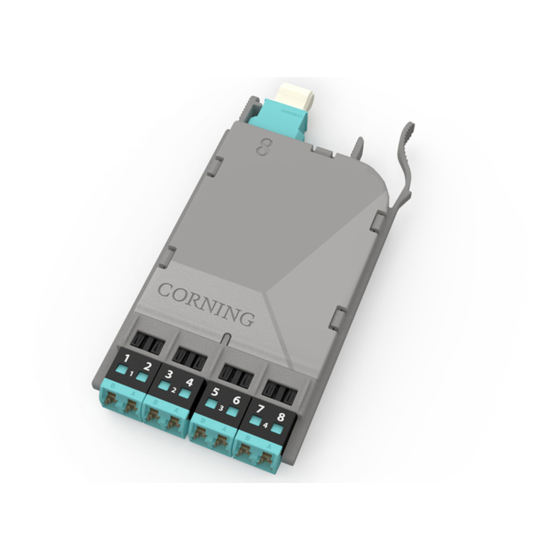
CORNING EDGE8 MTP Встановлення та тестування - Сторінка 13
Переглянути онлайн або завантажити pdf Встановлення та тестування для Блок управління CORNING EDGE8 MTP. CORNING EDGE8 MTP 13 сторінок. Tap module

10.4. To test the remaining portions of the system (Figure 17):
Step 1:
Install the Light Source/RJ1 LC connector adapter onto LC number 2 of the
harness plugged into the LIVE Port of the MTP Tap module.
Step 2:
Install Meter 1/RJ2's LC connector into the number 1 port of the EDGE8 module,
Module "B".
Step 3:
Install Meter 2/RJ3's LC connector adapter onto LC number 1 of the harness
plugged into the TAP port of the MTP Tap module.
Step 4:
Continue testing through on the even fibers of the harness plugged into the
front-mounted LIVE Port of the MTP Tap module using Tables 2 and 4 for testing
sequences.
LC #2
multimode only
RJ1
and
LC #8
adapter
Do NOT
disconnect
Light
Source
LC #1
RJ3
LC #8
and
adapter
Do NOT
disconnect
0.00 dB
M2
HPA-1007-EDGE8
Corning Optical Communications LLC • PO Box 489 • Hickory, NC 28603-0489 USA
800-743-2675 • FAX: 828-325-5060 • International: +1-828-901-5000 • www.corning.com/opcomm
Corning Optical Communications reserves the right to improve, enhance, and modify the features and specifications of Corning Optical Communications products
without prior notification. A complete listing of the trademarks of Corning Optical Communications is available at www.corning.com/opcomm/trademarks. All other
trademarks are the properties of their respective owners. Corning Optical Communications is ISO 9001 certified. © 2017 Corning Optical Communications. All
rights reserved.
STANDARD RECOMMENDED PROCEDURE 003-139-AEN | ISSUE 1 | JANUARy 2017 | PAGE 13 OF 13
Module harness
EDGE8 MTP Tap Module "A"
TAP port
test harness
"Near end"
Note: Fiber loss
depends on length
EDGE8 Module "B"
of system
RJ2
Do NOT
disconnect
0.00 dB
M1
"Far end"
