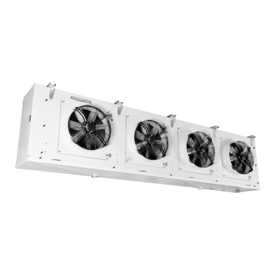
FRIMETAL FRB Інструкція з експлуатації - Сторінка 11
Переглянути онлайн або завантажити pdf Інструкція з експлуатації для Кондиціонер FRIMETAL FRB. FRIMETAL FRB 20 сторінок. Industrial evaporators

¡IMPORTANTE!
Los ventiladores disponen de un agujero, señalado por una
flecha, para la evacuación del agua. Este agujero debe que-
dar siempre situado en la parte de abajo para que pueda rea-
lizar su función.
DESCONGELACIÓN (1)
(1) SOLO PARA MODELOS CON ALGUNA DE LAS OPCIONES PARA
DESCONGELACIÓN
DESCONGELACIÓN ELÉCTRICA
El sistema de descongelación eléctrica incorpora los siguien-
tes elementos:
1 Resistencias blindadas en acero inoxidable y con los extre-
mos vulcanizados, introducidas y repartidas en el cuerpo de
la batería y bajo la bandeja de goteo interior.
2 Caja de conexiones a la que van conectadas las resisten-
cias con protección IP-55 situada en el extremo opuesto a
las conexiones frigoríficas.
Las conexiones están previstas para corriente de línea 400V
/ 3. La gama FR incorpora resistencias de 230V, por lo que se
van conectadas en estrella
GNH incorporan resistencias de 400V, por lo cual van conec-
tadas en triángulo
.
Se adjuntan los diagramas de conexiones correspondientes a
cada gama. Estos diagramas vienen también en una pegati-
na adherida al interior de la tapa de la caja de conexiones de
las resistencias.
, mientras que las gamas GR y
IMPORTANT!
The fan motors come with a hole, indicated by an arrow, for
water draining, which must always be situated on the lower
part of the motor to allow its use.
DEFROSTING (1)
(1) ONLY FOR MODELS WITH A DEFROSTING OPTION
ELECTRIC DEFROSTING
The electric defrosting system incorporates the following parts:
1 Heating elements encased in stainless steel tubes with both
ends vulcanised, inserted and distributed through the coil
and under the drainage pan.
2 Plastic junction box with IP-55 protection to which all the
heaters are connected. It is placed at the end side of the
evaporator opposite to the refrigerant connections.
The connections are due for a line current of 400V / 3.
Range FR incorporates 230V heating elements, thus they
are connected star
, while GR and GNH ranges incorpo-
rate heating elements of 400V, thus they have a delta
connection.
The diagrams with both kinds of connections are found atta-
ched. These diagrams may also be found on a label stuck on
the inner side of the junction box lid.
11
