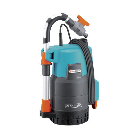
Gardena 1742 Інструкція з експлуатації Посібник з експлуатації - Сторінка 4
Переглянути онлайн або завантажити pdf Інструкція з експлуатації Посібник з експлуатації для Водяний насос Gardena 1742. Gardena 1742 14 сторінок. Rain water tank pump
Також для Gardena 1742: Інструкція з експлуатації Посібник з експлуатації (9 сторінок)

3. Assembly
Install / deinstall foot:
2
1
4. Initial Operation
Pumping water from
containers:
7
3
12
When the pump is to be used for draining for a flat container,
and is therefore placed on the ground, the foot can be
assembled so that the pump suctions less dirt. The stand is
included in the package.
Install foot:
v From below, place the foot
1
locks
click into place.
Deinstall foot:
v Press the two locks
The telescopic pipe
transport position. The telescopic pipe is fitted with a GARDENA
Regulator Valve. We recommend the use of a GARDENA
Standard Hose Connector: Art. No. 18215 for 13 mm (1/2") and
16 mm (5/8") and Art. No. 18216 for 19 mm (3/4") respectively,
for connecting a garden hose. With the use of 19-mm-(3/4")-
hose line, the pumping quantity is the greatest.
The length of the telescopic pipe
a manner that the pump does not touch the bottom of the con-
tainer; this way, dirt in the container is kept away from the pump.
1. Pull telescopic pipe
of the pump and screw onto the pump
4
connector
. Ensure that the washer
8
lies in the mating thread
telescopic pipe
2. Loosen threaded collars
telescopic pipe
3. Adjust telescopic pipe
of the container.
The telescopic pipe can be adjusted
between 73 – 91cm.
4. Turn threaded collars
firmly again.
5. Attach mains cable
7
ment clip
on the telescopic pipe
6. Hang pump with telescopic pipe
the container.
7. Insert the power plug.
ATTENTION! The pump begins operating immediately.
The shut-off valve
function of a water tap. With an open system (Micro-Drip-
System, Sprinklers), the hose may not be placed deeper
than the container as otherwise the water flows through the
pump from the container even when the pump is switched off.
2
on the pump until the two
1
and pull the foot
3
is placed on the side of the pump in the
3
should be adjusted in such
3
from the side
ß
of the
3a
3
.
5
of the
3
.
3
to the height
5
until they hold
6
with the attach-
3
.
3
into
8
in an operating pump takes on the
2
from the pump.
7
3
8
5
6
3a
z
4
