Garmin G500 Посібник - Сторінка 9
Переглянути онлайн або завантажити pdf Посібник для Дисплей авіоніки Garmin G500. Garmin G500 40 сторінок. Primary flight and multifuction display system
Також для Garmin G500: Короткий довідник (2 сторінок), Інструкція з експлуатації (14 сторінок)

Section 1. GENERAL
1.1
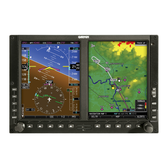
Garmin G500 Primary Flight / Multi-Function Display System
The G500 PFD/MFD System consists of a Primary Flight Display (PFD) and
Multi-Function Display (MFD) housed in a single Garmin Display Unit (GDU),
plus an Air Data Computer (ADC) and Attitude and Heading Reference System
(AHRS). The G500 interfaces with other installed systems in the aircraft,
including Garmin GPS/SBAS navigators, VHF navigation radios, Garmin GDL
69 data link radios, Garmin GSR 56 Iridum transceivers, and various weather
radars, audio panels, video sources, radar altimeters, traffic systems and ADF
navigators.
The primary function of the PFD is to provide attitude, heading, air data and
navigation information to the pilot. The primary function of the MFD is to
provide mapping, terrain, and flight plan information.
The standby instruments (altimeter, airspeed, attitude, and magnetic compass)
are completely independent from the PFD and will continue to operate in the
event the PFD is not usable. These standby instruments should be included in
the pilot's normal instrument scan and may be referenced if the PFD data is in
question. A second G500 system installed on the co-pilot's side does not require
additional standby instruments.
1.2
System Power Sources
The G500 system depends on electrical power to maintain proper operation. The
Garmin Display Unit (GDU), Attitude and Heading Reference System (AHRS),
and Air Data Computer (ADC) are directly tied to the aircraft's main or essential
bus and energized when the aircraft master switch is turned on. Other systems,
like the navigation equipment, weather datalink, autopilot and Adapter (GAD)
are typically located on the avionics bus and may not be operable during engine
start.
The major components of the G500 are circuit breaker protected with resettable
type breakers available to the pilot. These breakers are located at the main or
essential bus circuit breaker panel and labeled as follows:
1.
PFD
2.
AHRS -
3.
ADC
4.
GAD
5.
STBY ATT- Electric Standby Attitude Gyro
In dual installations the pilot side equipment is suffixed with the number 1 and
the copilot side equipment is suffixed with the number 2. For example: PFD 1
and PFD 2.
AFMS, GARMIN G500 PFD/MFD SYSTEM
FAA APPROVED
-
Garmin Display Unit (PFD/MFD), GDU 620
Attitude and Heading Reference System, GRS 77
-
Air Data Computer, GDC 74A
-
Garmin Adapter, GAD 43/43e (optional)
190-01102-01 Rev. 9
Page 9 of 40
