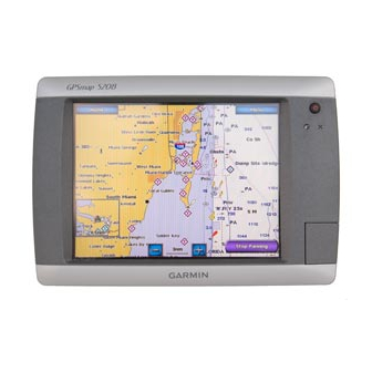
Flush Mounting the GPSMAP 4000/5000 Series Chartplotter
The flush-mount method you will use with your chartplotter is dependent on the model. Be sure to follow the instructions for your chartplotter
model.
Flush Mounting a GPSMAP 4008/4208/4012/4212 Chartplotter or a GPSMAP 5008/5208/5012/5212
Chartplotter
Hardware (included):
• Flush-mount template
• Rubber gasket
• Four threaded 4 mm mounting studs
• Four 4 mm flat washers
• Four 4 mm lock washers
• Four 4 mm nuts
to flush mount a GPSMAP 4008/4208/4012/4212 chartplotter or a GPSMAP 5008/5208/5012/5212 chartplotter:
1. The flush-mount template is included in the product box. Trim the template and ensure it will fit in the location at which you want to flush
mount the chartplotter.
NOTES:
• Make sure the surface on which you mount the chartplotter has at least 7 in. (18 cm) of open space behind it to fit the chartplotter and the
connected wires.
• Make sure to leave approximately 1/2 in. (13 mm) of space on the right side of the chartplotter to access the SD card door.
• Mount a 4008/4208/5008/5208 chartplotter 31 1/2 in. (80 cm), and a 4012/4212/5012/5212 chartplotter 39 3/8 in. (1 m) from a magnetic
compass to avoid interference.
2. The flush-mount template has adhesive on the back. Remove the protective liner and apply the template to the mounting location.
3. Using a
/
in. (10 mm) drill bit, drill one or more of the four pilot holes inside the corner of the template to begin cutting the mounting surface.
3
8
4. Using the jigsaw, cut the mounting surface along the inside of the solid line indicated on the flush-mount template. Use a file and sandpaper
to refine the size of the hole.
Be very careful when cutting this hole. There is only a small amount of clearance between the case and the mounting holes.
5. Install the four mounting studs by screwing them into the back of the chartplotter. Use the
studs until they stop. The studs are coated with a reusable thread-locking patch applied at the factory.
Do not use power tools to tighten the mounting studs. Doing so may cause you to overtighten.
Do not overtighten - you may damage the mounting stud or the mounting holes.
6. Place the chartplotter in the hole and make sure that the mounting studs line up with the pilot holes on the flush-mount template after cutting,
sanding, and filing the hole. If they do not, mark the locations where the studs will feed through the mounting surface.
7. Using the center punch, indent the center of each of the 4 mm mounting-hole locations.
8. Using a 4 mm drill bit, drill the four mounting holes.
9. Install the rubber gasket on the back of the chartplotter. The top and bottom sections will line up with the holes. The side sections will line up
with the notches in the case (for the cover).
10. P lace the chartplotter into the cutout. The four mounting studs should feed through the four mounting holes drilled in step 8.
11. P lace the flat washers and the lock washers over the mounting studs. Then thread the hex nuts onto the mounting studs. Tighten all four hex
nuts evenly until the chartplotter is snug against the mounting surface.
GPSMAP 4000/5000 Series Installation Instructions
tools required (not included):
• Jigsaw
• Masking tape
• Scissors
• Drill
• Drill bits—
/
in. (10 mm) and 4 mm
3
8
•
/
in. (2 mm) Allen (Hex) wrench
1
16
• 4 mm socket or wrench
• Center punch and hammer
notice
/
1
16
notice
in. (2 mm) Allen wrench to tighten the mounting
3

