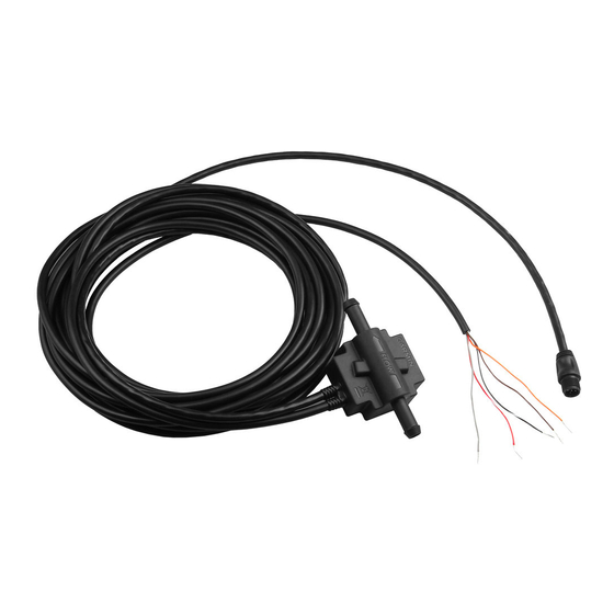
Step 1: Installing the GFS 10 in the Fuel Hose
Ensure that the fuel hose is drained, and use a hose cutter or a knife to cut the fuel hose where you want to install the GFS 10. Use the included
hose clamps to secure the fuel hose to the GFS 10. Do not overtighten the clamps. Inspect your fuel system and connections regularly.
Notes:
• Install the GFS 10 as far from the engine as practical.
Do not install the GFS 10 directly on the engine or where
it could be subjected to excessive heat or vibration. Do not
install the GFS 10 between the engine and the priming
bulb (if applicable).
• When placing the GFS 10 in the fuel hose, be sure the
direction of flow, as indicated by the arrow, points toward
the engine.
• Install the GFS 10 so the fuel flows in an upward direction
through the GFS 10. This will prevent errors caused by air
bubbles.
• Install the GFS 10 in a location above the maximum fuel level of the fuel tank.
• Install the included fuel filter in the fuel hose between the fuel tank and the GFS 10. A sticker on the filter indicates the direction of fuel
flow. Always have a spare metal
• If additional fuel hose is needed when installing the GFS 10 and fuel filter, use
• Have two
/
in. (9.5 mm) in-line, fuel-line splice barbs available. This allows you to remove the GFS 10 and the fuel filter, in case of an
3
8
emergency, and maintain normal engine operation.
• Be sure to clean up any spilled fuel.
Step 2: Mounting the GFS 10 and Fuel Filter
The GFS 10, the in-line fuel filter, and the fuel hoses must be mounted to your boat. A bracket for the GFS 10, cable ties with eyelets for the
in-line fuel filter and hoses, and mounting screws are provided.
When mounting the GFS 10 to a solid structure on your boat, use the included bracket to secure the GFS 10 device, and use two included cable
ties to secure the hose on either side of the GFS 10. When mounting the in-line fuel filter to a solid structure on your boat, use two cable ties
around the fuel filter and two cable ties around the hose on either side of the fuel filter. If you are unable to use the included bracket to secure
the GFS 10 to a solid surface, use an included cable tie to secure the GFS 10 device to a bundle of cables or other hoses.
Use the included screws to mount the GFS 10 and the in-line fuel filter. Drill a
If you are mounting the GFS 10 on fiberglass, use a countersink bit to drill a clearance counterbore through the top
gelcoat layer (but no deeper). This will help to avoid cracking in the gelcoat layer when the screws are tightened.
2
/
3
in. (9.5 mm) in-line fuel filter available.
8
Engine
To power and
data connections
/
3
in. (9.5 mm) US Coast Guard type A1 fuel hose.
8
/
in. (3.2 mm) pilot hole for each screw.
1
8
GFS 10
Fuel filter
Fuel tank
GFS 10 Fuel Sensor Installation Instructions
Bracket
Cable
tie (×6)

