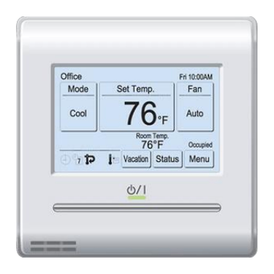
Fujitsu UTY-RNRUZ2 Посібник з монтажу - Сторінка 4
Переглянути онлайн або завантажити pdf Посібник з монтажу для Кондиціонер Fujitsu UTY-RNRUZ2. Fujitsu UTY-RNRUZ2 11 сторінок. Remote controller (wired type)
Також для Fujitsu UTY-RNRUZ2: Посібник з експлуатації (26 сторінок)

5.2.3. Setting the DIP switch
Use an insulated screwdriver to set the DIP switches. Do not touch the
DIP switch with your hands.
Before using this product, always set DIP switch to "ON". If not set, when
the main power is turned on again, the set data by menu operation will be
erased and cause erroneous operation.
[DIP Switch]
• Performs the enabling/disabling of the backup function by the internal
battery.
• It is disabled when shipped from the factory to prevent consumption of
the charge.
5.3. Installation
Perform wiring so that water does not enter this unit along the external
wiring. Always install a trap to the wiring or take other countermeasures.
Otherwise it will cause trouble or electric shock or fire.
5.3.1. Install the rear case
A. When attaching to switch box:
Seal the wiring hole of the remote controller
cable with putty.
Trap (remote controller cable)
Box
Rear case
B. When attaching to the wall directly:
Wall
Seal the wiring hole of the remote controller
cable with putty.
Rear case
Trap (remote controller cable)
C. When routing the cable on-wall:
Cut off
Rear case
En-4
CAUTION
Front case (back side)
Set the DIP switch to ON
OFF ON
CAUTION
Connector
Putty
Screws
Trap
Connector
Putty
Screws
Trap
Cable cover
(more than
1 mm thick)
Epoxy putty
5.3.2. Connecting the remote controller cable
When connecting a remote controller cable to the remote controller
terminal block, please use the specified torque to tighten screws. If you
over-tighten screws, they will break the terminal unit.
Be careful to avoid breaking the cable by over-tightening the cable tie.
Tightening torque
Fasten the outside covering of the connection cable with the cable tie.
Tighten the cable tie firmly so that pulling force does not propagate to the
terminal connection even if force of 30 N is applied to the cable.
Select a flexible cable that can be bound using cable ties from over the
cable sheath inside this unit.
Cable tie
GOOD
5.3.3. Attach the front case
Connect the remote controller cable connector to
the connector of the front case PC board. Insert
after adjusting upper part of front case. Otherwise,
there is a risk of damage to the internal parts of this
unit. When you attach the front case, make sure that
the cables are not being pinched by front case.
5.4. Connecting to the indoor unit
When connecting the remote controller cable to the indoor unit, do not
connect it to the outdoor unit or the power terminal block. It may cause a
failure.
When switching the DIP switch (SW1) on the indoor unit PC board, be
sure to turn off the power supply to the indoor unit. Otherwise, the PC
board of the indoor unit may be damaged.
There are 2 methods to connect the remote controller cable to the indoor
unit. One is the connection using connecting cable (Included in the indoor
unit), and the other is the connection the remote controller cable is con-
nected to the exclusive terminal block of the indoor unit.
(For the details, refer to the installation manual of the indoor unit to be
used.)
5.4.1. When connecting to the connector
(1) Use a tool to cut off the terminal on the end of the remote controller
cable, and then remove the insulation from the cut end of the cable as
shown in Fig. 1. Connect the remote controller cable and connecting
cable as shown in Fig. 2. Be sure to insulate the connection between
the cables.
Fig.1
Fig.2
13/16 in
Insulated
(20 mm)
connection
Remote control-
ler cable (Non-
polar)
(2) Connect the remote controller cable to the connecting cable, and
insert it to the connector. Set to "2WIRE" the DIP switch (SW1) on the
PC board of the indoor unit.
CAUTION
7.1 to 10.6 lbf•in (0.8 to 1.2 N•m)
PROHIBITED
(1)
(2)
CAUTION
White
Connecting
cable
Red
Black
Cut and
terminate
