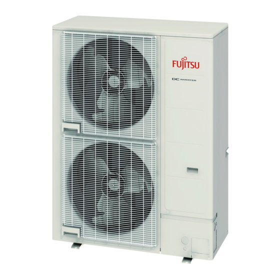
Fujitsu Waterstage WOYK150LJL Посібник з монтажу - Сторінка 10
Переглянути онлайн або завантажити pdf Посібник з монтажу для Кондиціонер Fujitsu Waterstage WOYK150LJL. Fujitsu Waterstage WOYK150LJL 16 сторінок. Air to water heat pump outdoor unit

(3) Use the specifi ed wires, connect them securely, and fasten them so that there is no
stress placed on the terminals.
(4) Use an appropriate screwdriver to tighten the terminal screws. Do not use a
screwdriver that is too small, otherwise, the screw heads may be damaged and
prevent the screws from being properly tightened.
(5) Do not tighten the terminal screws too much, otherwise, the screws may break.
Screw with special washer
Ring terminal
Wire
Terminal blocks
(6) See the table below for the terminal screw tightening torques.
Tightening torque [N·m (kgf·cm)]
M4 screw
M5 screw
6.3. Knock out holes for wiring
Be careful not to deform or scratch the panel while opening the knockout holes.
After opening the knockout holes, remove burr on the edges, and attach the one-touch
bush (accessory), grommet or conduit etc. to prevent damaging the cables.
It is recommended to apply rust proof paint on the edges to prevent rust.
Knockout holes are provided in front and lateral sides for wiring.
Ø50
Ø34.5
Ø22.2
Length of the grommet edging
L
Knockout hole
Dimension L
diameter (mm)
(mm)
Ø 50
147
Ø 34.5
100
Ø 22.2
60
6.4. Wiring method
6.4.1. Connection diagrams
EARTH
L1
L2
L3
N
1
2
3
EARTH
Outdoor unit
side terminal
En-9
Screw with
special washer
Ring terminal
Wire
1.2 to 1.8 (12 to 18)
2.0 to 3.0 (20 to 30)
CAUTION
Ø50
Ø34.5
Ø22.2
Mounting the grommet edging
Knockout hole
Grommet edging
(accessories)
POWER SUPPLY
(R)(S)(T)(N)
1
2
3
EARTH
Indoor unit
side terminal
6.4.2. Connection cable preparation
• Keep the earth wire longer than the other wires.
Earth wire
6.4.3. Wiring procedure
(1) Remove the service panel, the terminal cover and connect the wires to the terminal
in accordance with the terminal nameplate. (Fig. A, Fig. B)
(2) Secure the cables using the cable clamps under the terminal blocks. (Fig. B)
• Connect the wires without applying excessive tension.
(3) Secure the cables using the cable ties at the base of the valves. (Fig. A)
Fig. A
Unit: mm
Cable tie
Fig. B
Power supply cable
(4) Be sure to install the terminal cover after the wiring is complete.
30 mm
Power supply cable or
Connection cable
35 mm
Push mount
cable tie
Power supply
(accessory)
cable
Connection cable
Terminal blocks
Terminal blocks
Terminal nameplate
L1 L2 L3 N 1 2 3
POWER
INDOOR UNIT
Connection cable
(indoor unit and
outdoor unit con-
nection cable)
