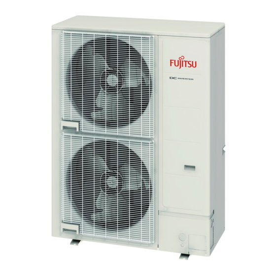
Fujitsu Waterstage WOYK150LJL Посібник з монтажу - Сторінка 6
Переглянути онлайн або завантажити pdf Посібник з монтажу для Кондиціонер Fujitsu Waterstage WOYK150LJL. Fujitsu Waterstage WOYK150LJL 16 сторінок. Air to water heat pump outdoor unit

• Do not install directly on the ground, this may result in equipment failure.
• The drain water is discharged from the bottom of the equipment. Construct a drain ditch
around the base and discharge the drain water properly
• Provide ample space for ice buildup from condensate between the bottom of the unit and
the flat surface on which it is mounted. Otherwise, there is risk that the drainage water
will freeze between the device and the surface, disabling drainage.
If the unit is installed in a region that is exposed to
high winds, freezing conditions, freezing rain, snow
fall or heavy snow accumulation, take appropriate
measures to protect it from those elements.
To ensure stable operation, the outdoor unit must be
installed on a raised stand or rack, at or above the
anticipated snow depth for the region.
The installation of snow hoods and drift prevention
fencing is recommended when blowing and drifting
snow is common to the region.
Base
4. PIPE SELECTION
4.1. Selecting the pipe material
Do not use existing pipes.
Use pipes that have clean external and internal sides without any contamination which
may cause trouble during use, such as sulfur, oxide, dust, cutting waste, oil, or water.
It is necessary to use seamless copper pipes.
Material: Phosphor deoxidized seamless copper pipes.
It is desirable that the amount of residual oil is less than 40 mg/10 m.
Do not use copper pipes that have a collapsed, deformed, or discolored portion
(especially on the interior surface).
Otherwise, the expansion valve or capillary tube may become blocked with contaminants.
Improper pipe selection will degrade performance. As an air conditioner using R410A
incurs pressure higher than when using conventional refrigerant, it is necessary to
choose adequate materials.
• Thicknesses of copper pipes used with R410A are as shown in the table.
• Never use copper pipes thinner than those indicated in the table even if they are
available on the market.
Table. A
(Wall thickness and pipe material for each diameter)
Outside Diameter
mm
Wall Thickness *2
mm
COPPER *1
Material
JIS H3300 C1220T-O or equivalent
Please select the pipe size in accordance with local rules.
*1: Allowable tensile stress ≥ 33 (N/mm
*2: Endurance pressure of the pipes 4.2MPa
4.2. Protection of pipes
• Protect the pipes to prevent the entry of moisture and dust.
• Especially, pay attention when passing the pipes through a hole or connecting the
end of a pipe to the outdoor unit.
Location
Working period
1 month or more
Outdoor
Less than 1 month
Indoor
4.3. Refrigerant pipe size and allowable piping length
Keep the piping length between the indoor unit and outdoor unit within the allowable
tolerance.
Pipe diameter <Liquid/Gas> [mm (in.)]
Max. piping length (L)
Min. piping length (L)
Max. height difference <H1/H2>
<Indoor unit to outdoor unit>
View (Example)
*: For the standard pipe diameter.
En-5
CAUTION
CAUTION
6.35
9.52
12.70
15.88
0.8
0.8
0.8
1.0
)
2
Protection method
Pinch pipes
Pinch or tape pipes
-
Pinch or tape pipes
CAUTION
9.52 (3/8) / 15.88 (5/8)
[m]
30*
[m]
5
15 / 25
[m]
L
H
1
5. PIPE INSTALLATION-1
5.1. Opening a knock out hole
Be careful not to deform or scratch the panel while opening the knock out holes.
To protect the piping insulation after opening a knock out hole, remove any burrs from
the edge of the hole. It is recommended to apply rust prevention paint to the edge of
the hole.
• Pipes can be connected from 3 directions, front, lateral side and bottom. (Fig. A)
• When connecting at the bottom, remove the service panel and piping cover on the front
of the outdoor unit, and open the knockout hole provided at the bottom corner of the
piping outlet.
Fig. A
19.05
1.2
Front connection
• It can be installed as shown on "Fig. B" cutting out the 2 slits as indicated on "Fig. C".
(When cutting slits, use a steel saw.)
Fig. B
Slit
5.2. Brazing
If air or another type of refrigerant enters the refrigeration cycle, the internal pressure in
the refrigeration cycle will become abnormally high and prevent the unit from exerting
its full performance.
Apply nitrogen gas while brazing the pipes. If a pipe is brazed without applying nitro-
gen gas, an oxidation fi lm will be created.
This can degrade performance or damage the parts
in the unit (such as the compressor or valves).
Nitrogen gas pressure: 0.02 MPa
(= pressure felt suffi ciently on the back of the hand)
H
2
L
CAUTION
Service panel
94
21
60 12
Lateral connection
Fig. C
Slit
CAUTION
21
92
Top view of
the base
Unit: mm
Bottom connection
Bottom
connection
Pressure regulating valve
Cap
Nitrogen gas
Brazing area
