Kohler GM87448 Операція - Сторінка 21
Переглянути онлайн або завантажити pdf Операція для Портативний генератор Kohler GM87448. Kohler GM87448 24 сторінки. Industrial generator set

Periodically clean both battery terminals with baking soda and tighten all connections. No other maintenance on the battery
charger is required.
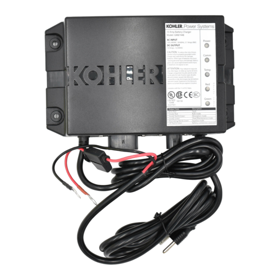
This section describes general troubleshooting for the battery charger. Use the following troubleshooting procedure and the
LED indication chart to verify power, communication, and look for wiring harness shorts and grounds. Use the LED indicator
lights, SiteTech™, or the controller user interface to see what state or fault is indicated. Refer to the LED Indication chart.
1.
Check the generator set controller for faults related to the battery charger.
a.
BatteryCharger1CommLoss – Loss of communication to battery charger 1.
b.
BatteryCharger2CommLoss – Loss of communication to battery charger 2.
c.
BatteryChargerFault – There is a general issue with the battery charger (high battery temperature, low
battery temperature, absorption timeout triggered).
d.
BatteryFault – There is an issue with the battery.
e.
BatteryChargerIdentityConflict – There is a CAN address conflict.
i. Check ID selection jumper on the engine harness. Refer to the wiring diagram.
f.
ChargerParameterMismatch – The controller parameter value does not match what was accepted by the
battery charger.
i. Verify that parameter values are correct.
2.
Check the battery charger power supply. If the Power LED is off (indicating no power supply):
a.
Use a voltmeter to verify the power source is providing the appropriate voltage.
b.
Check the AC power leads for breaks and shorts.
c.
Check the fuse. Replace if needed. Check the fuse holder contact points for corrosion.
3.
Check the CAN communication with the controller.
a.
If the Communication LED on the charger is blinking or not active (off):
i. Check the CAN lines for breaks or shorts.
ii. Check network impedance. Impedance should measure 60 ohms on an inactive network that is
iii. Check the controller to ensure that the proper generator profile is installed and the correct engine
b.
If the Communication LED on the charger is solid:
i. Wait 10 seconds and check the Communication LED for a state change.
ii. Clear the fault on the controller.
4.
Check the temperature compensation. If the Temperature LED is blinking or not active (off):
a.
Use SiteTech™ or the controller user interface to verify that temperature compensation is enabled and the
battery topology is correct.
Note: Verifying the parameter settings is important when using a battery type other than flooded lead acid
(FLA).
b.
Verify that the temperature sensor connections are secure and check the wiring leads for breaks or shorts.
c.
If problems persist, replace the temperature sensor.
5.
Check the output voltage.
a.
If the red Output State LED is blinking (indicating a charger or battery fault condition exists):
i. Use SiteTech™ or the controller user interface to verify that the correct parameter settings are
ii. Check the fuse. Replace if needed. Check the fuse holder contact points for corrosion.
iii. Check the battery terminal temperature. The battery charger produces a fault when battery
iv. Use a voltmeter to verify that the battery charger is producing the correct voltage for the charge
6.
Verify that the battery is the correct size.
7.
Verify that the battery is functioning properly and can accept a charge. Check the electrolyte levels. Replace the
battery if needed.
8.
Verify that the controller is functioning properly and receiving CAN communication.
9.
If a problem still exists, replace the battery charger.
TP-7077
3/19
properly setup.
profile is selected.
used (pay close attention to charger system voltage and battery topology).
Note: Verifying the parameter settings is important when using a battery type other than flooded
lead acid (FLA).
temperature conditions are too hot or too cold for effective charging.
state (Bulk, Absorption, Float, etc.) that the battery has entered. Reference the Default Settings in
the parameter chart.
Section 4. Maintenance
Section 5. Troubleshooting
21
