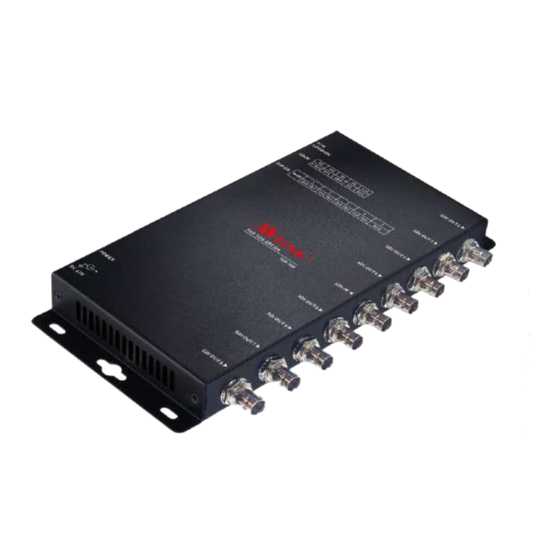
AVLink 12S-104 Посібник користувача - Сторінка 2
Переглянути онлайн або завантажити pdf Посібник користувача для Підсилювач AVLink 12S-104. AVLink 12S-104 2 сторінки.
Також для AVLink 12S-104: Посібник користувача (2 сторінок)

2. Plug the extension cables from video source device (Ex
Camcorders or Pattern Generator) into the SDI IN port
connectors.
3. Plug the power adapter into the wall socket.
4. Turn on the monitor first.
5. Turn on the Camcorders or Pattern Generator.
Operation
1. Make sure 'POWER' Led turn on when you plug-in AC
adaptor outlet.
2. Make sure 'LOCK LED' turn on when you ready signal
source.
Note:
Please check cable/power when you ready everything but
LOCK LED is off.
Assembly application diagram:
12S-104
12S-108
-3-
DIP Switch List of Settings
12S-104
1
2
Output
Output
ON
1&2
3&4
ON
ON
Output
Output
OFF
1&2
3&4
OFF
OFF
※Factory Defaults to 1&2 ON.
12S-108
1
2
3
Output
Output
Output
ON
1&2
3&4
5&6
ON
ON
ON
Output
Output
Output
OFF
1&2
3&4
5&6
OFF
OFF
OFF
※Factory Defaults to 1~4 ON.
Lock LED List of Colors
COLOR
SDI IN signal
LIGHT BLUE
SD
PURPLE
HD
GREEN
3G
YELLOW
6G
BLUE
12G
Firmware Upgrade:
Micro USB
1.
Connect Power Jack
2.
Connect Micro USB
3.
Put Bin File in Start Folder.
4.
Execute Firmware Upgrade.exe
-4-
3
Output
Amp
ON
Output
Amp
OFF
4
5
5.
Check Link State (Red: Disconnect Green: Connected)
Output
Output
6.
Select Bin File
7&8
Amp
7.
Press Confirm to Upgrade
ON
ON
Output
Output
7&8
Amp
OFF
OFF
8.
Check Progress Bar value is 100 and Command Success
※
Firmware upload utility software from AVlink's official
website.
Power
© AV LINK GROUP LTD. All rights reserved.
Trademarks:
All the companies, brand names, and product names
referred to this manual are the trademarks or
registered trademarks belonging to their respective
companies.
-5-
