DFRobot DFR0285 Посібник із швидкого старту - Сторінка 3
Переглянути онлайн або завантажити pdf Посібник із швидкого старту для Материнська плата DFRobot DFR0285. DFRobot DFR0285 4 сторінки.

Pinout
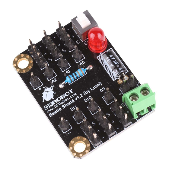
The shield is a breakout of the six pins D9, D10, D11 and A0, A1, A2 as well the two power pins +
and – besides the USB socket. The other two power pads on the other side of the Beetle are not
connected with the shield but you still can use them as a power source since they are routed to the
power lines on the Beetle itself.
Beetle shield pinout (click to enlarge)
After soldering the Beetle on the shield you may power it up by connecting a power source from 3V
to 5V with the power pins labeled with + and - on the Beetle shield. With switching the power on by
pressing the button the LED should light up to confirm the power is witched on. At the same time the
LED on the Beetle should light up too. That is the proof that you successful finished the soldering
task.
Now you might program your Beetle controller by connecting a Micro USB cable with the USB
socket of the Beetle.
The pins on the Beetle shield are arranged to connect with standard servo and sensor connectors.
The order is as followed:
Signal VCC GND
Note: If you want to use the additional pins (RX, TX, SCL and SDA) broken out to the Pads on the
backside of the Beetle controller you might need to solder them before you solder the Beetle to the
shield.
