ensto ECO10F Посібник з монтажу та експлуатації - Сторінка 4
Переглянути онлайн або завантажити pdf Посібник з монтажу та експлуатації для Терморегулятор ensto ECO10F. ensto ECO10F 12 сторінок.

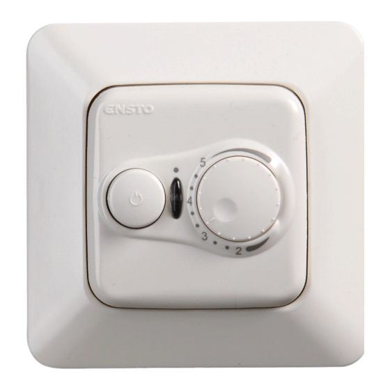
ECO10F and ECOINTRO10F Floor Thermostat
ENG
Installation and Operating Instructions
1.
Introduction
ECO10F and ECOINTRO10F floor thermostats are for room-specific control of electric floor heating.
2.
Safety instructions
Electrically skilled person
•
The installation must only be done by an electrician with the appropriate qualifications.
•
Read this manual carefully before starting the installation work.
•
Follow the instructions in this manual, and make sure that the installation complies with na-
tional safety regulations, installation methods and restrictions.
•
The information provided in this manual in no way exempts the installer or user from responsi-
bility to follow all applicable safety regulations.
•
This manual is a part of the product and must be stored in a safe location so that it is available
for future installation and service.
WARNING
Danger of electric shock! Risk of fire!
•
Disconnect the power supply before carrying out any installation or maintenance work on this ther-
mostat and associated components.
•
Do not switch on the power supply before the installation work is completed.
•
Improper installation can cause personal injury and property damage.
•
Do not operate a defect thermostat.
3.
Before installation
3.1. Make sure that all the parts and tools needed for the installation are available.
3.2. Make sure that heating load is equivalent to the thermostat power endurance.
3.3. Measure the insulation resistance and circuit resistance of the heating load controlled by the thermo-
stat.
4.
Installation, figures 1, 2 and 4
4.1. Mount the thermostat as the cover of a 1-component mounting box or as a part of a multiple-
component instrument panel.
4.2. Place the sensor cable in a dry protective tube between heating cables.
NOTE! Make sure that there is not water in the protective tube.
4.3. Connect the earthing wires (PE) to the separate connector.
4.4. Connect the thermostat to the mains and load according to figures 1 and 2.
•
Connect the supply conductors. The stripping length is 9 mm.
•
Connect the sensor cable to the sensor marked connector. The stripping length is 7 mm.
•
The thermostat has spring connectors. Disconnected the conductors from the spring connectors by
twisting and pulling at the same time.
•
Use a residual circuit breaker according to local installation regulations.
4.5. Install the thermostat into the mounting box with screws.
4.6. Install the thermostat lid, cover plate and adjustment knob. Cover the thermostat from potential
dust during construction work.
4 / 12
RAK40 / 3.5.2021
