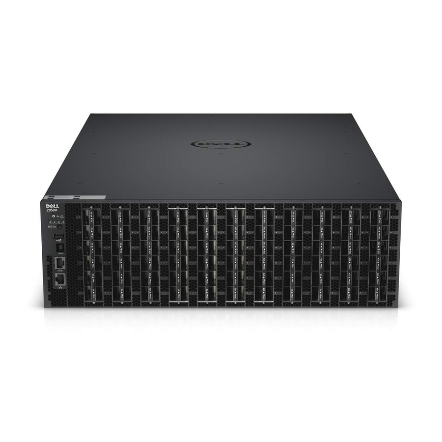
Dell Networking Z9500 Посібник з монтажу - Сторінка 35
Переглянути онлайн або завантажити pdf Посібник з монтажу для Перемикач Dell Networking Z9500. Dell Networking Z9500 47 сторінок. Z9500 switch
Також для Dell Networking Z9500: Посібник для початківців (34 сторінок)

Installing the Cable Management System for Optical Fibres
Insert an optical cable in a Z9500 port. then route the optical cable up and along the line-card face
above the switch. Position the cables so they follow the channel marked in the figure below and exit
to the right or left, depending on the chassis slot location. The cables should emerge from right and
left side of the panel.
Figure 13. Routing Optical Fibres using the Cable Management System
1.
Rack unit to be installed only for optical
cables
NOTE: When the switch operates in the supported temperature range, LR4 optics can be used
only in the upper half of the ports on the switch:
•
Line card 0 — only in ports 12, 16, 20, 36, 40, 44, 60, 64, 68, 84, 88, 92, 108, 112, 116, 132,
136, and 140.
•
Line card 1 — only in ports 12, 16, 20, 36, 40, 44, 60, 64, 68, 84, 88, 92, 108, 112, 116, 132,
136, 140, 156, 160, 164, 180, 184, and 188.
•
Line card 2 — only in ports 12, 16, 20, 36, 40, 44, 60, 64, 68, 84, 88, 92, 108, 112, 116, 132,
136, 140, 156, 160, 164, 180, 184, and 188.
When the switch operates in a reduced ambient temperature, you can use LR4 optics in any
port. See
Port Numbering Convention
Installing the QSFP+ Optics
The switch has 132 QSFP+ optical ports, which can be used with breakout cables for 528 small form-
factor pluggable plus (SFP+) optical ports.
For a list of supported optics, contact your Dell Networking representative or reseller.
CAUTION: ESD damage can occur if the components are mishandled. Always wear an ESD-
preventive wrist or heel ground strap when handling the switch and its components.
Z9500 Installation
2.
Z9500 switch
for an illustration that shows port location.
35
