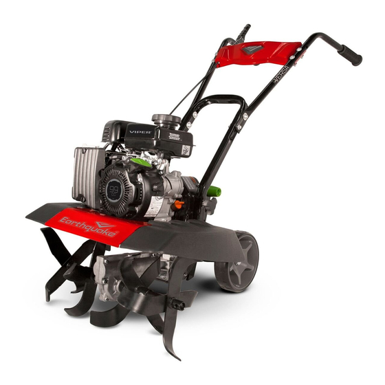
EarthQuake VERSA 20015 SERIES Посібник користувача - Сторінка 7
Переглянути онлайн або завантажити pdf Посібник користувача для Румпель EarthQuake VERSA 20015 SERIES. EarthQuake VERSA 20015 SERIES 13 сторінок. Compact tiller and cultivator

LOCK PIN HINGE
LOCK PIN INSTALLED CORRECTLY
NOTE: Ensure the lock pins and tines are correctly installed. Lock pins must be installed so that the pin enters the hole in the
tine from the front of the tiller, and so the wire bale hinges over the top of the tine pipe and latches to the protruding pin on
the back side of the tine. Tines can inadvertently detach during tilling if lock pins are not installed correctly!
I
L
G
C
Check that arrows are pointing in the direction of forward
rotation and slide left tine set over tine shaft sleeve, align
mounting holes with the left tine shaft, and secure with
the M10 x 45 mm Hex Bolt, Spring Lock Washer, and Ny-
lock Nut. Tighten with two 15mm wrenches. Repeat for
right tine set on right tine shaft.
FIGURE 6 (FOR MODELS 20015/24734)
12
Get parts online at www.GetEarthquake.com or Call 800-345-6007 M-F 8-5 CST
VERSA COMPACT TILLER AND CULTIVATOR
LOCK PIN INSTALLED INCORRECTLY
FIGURE 5A
2X
13
mm
Align lower handlebar assembly mount holes with lower
mount holes on pulley box. Place one M8 x 25 mm Flat
Washer on one M8 x 40 mm Hex Bolt and insert through
lower mount hole of lower handlebar assembly and pulley
box. Place one M8 Nylock Nut on bolt and tighten with
two 13mm wrenches. Repeat for other side.
FIGURE 6A (FOR MODELS 20015/24734)
Owner's Manual
Tine side shield installation:
a.
Remove hand knob bolts from lower handlebar assembly.
b. Rotate lower handlebar assembly away from engine to provide adequate clearance to install side tine shields.
H F
A
Rotate lower handlebar assembly away from engine to provide adequate clearance to install side tine shields Slide left and
right side shields onto center tine shield. Align side shield grooves with center tine shield and push until an audible click is
heard and/or felt. This indicates that the tine shield has engaged with the shield lock and is secured all the way on. Rotate
lower handlebar assembly up towards engine and insert hand knob bolts through upper mount holes and tighten.
NOTE: Hand knob bolts can be inserted into one of two sets of holes depending on desired handlebar height.
REMOVE
HAND
KNOBS
FIGURE 7A (FOR MODELS 25780/29241)
1st
2nd
FIGURE 7B
Get parts online at www.GetEarthquake.com or Call 800-345-6007 M-F 8-5 CST
Owner's Manual
VERSA COMPACT TILLER AND CULTIVATOR
13
