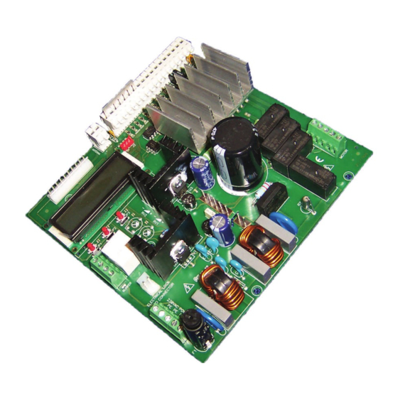
Allmatic CT INVERTER AM Посібник з монтажу - Сторінка 3
Переглянути онлайн або завантажити pdf Посібник з монтажу для Блок управління Allmatic CT INVERTER AM. Allmatic CT INVERTER AM 12 сторінок. Programmable control board for sliding gates with inverter technology

2. Collegamenti
1
2
3
4
5
6
7
8
9
10
11
6-1622595
rev.06
13/01/2017
ANTENNA INPUT
Connect the signal cable of the antenna to the
clamp 1 of the terminal board.
Connect the ground of the antenna to the clamp
2 of the terminal board.
STEP BY STEP INPUT
Connect the STEP-BY-STEP BUTTON (S.S.)
between the clamps 3 and 4.
ATTENTION: leave it open if not used
PHOTOCELL INPUT
Connect the
NORMALLY CLOSED contact
of the photocell (PHOTO) between the clamps 3
and 5 of the terminal board.
ATTENTION: jumper the inputs if not used
STOP INPUT
Connect the contact NORMALLY CLOSED of
the STOP between the clamps 3 and 6 of the
terminal board.
ATTENTION: jumper the inputs if not used
SAFETY EDGE INPUT
Connect the contact NORMALLY CLOSED of
the SAFETY EDGE between the clamps 3 and
7 of the terminal board.
ATTENTION: jumper the inputs if not used
INPUT CLOSING LIMIT SWITCH
Connect the contact NORMALLY CLOSED of
the CLOSING LIMIT SWITCH (L.S.CL.) between
the clamps 3 and 8 of the control board.
INPUT OPENING LIMIT SWITCH
Connect the contact NORMALLY CLOSED of
the
OPENING
LIMIT
SWITCH
between the clamps 3 and 9 of the terminal
board.
PARTIAL OPENING INPUT
Connect the PARTIAL OPENING button (PED.)
between the clamps 3 and 10 of the terminal
board.
ATTENTION: leave it open if not used
OPEN INPUT
Connect the button OPEN between the clamps
3 and 11 of the terminal board.
ATTENTION: leave it open if not used
CLOSE INPUT
Connect the button CLOSE between the clamps
3 and 12 of the terminal board.
ATTENTION: leave it open if not used
ENCODER INPUT
Connect the SIGNAL cable of the encoder to the
clamp 13 of the terminal board.
Connect the GND cable of the encoder to the
clamp 14 of the terminal board.
Connect the cable +Vdc of the encoder to the
clamp 15 of the terminal board.
ATTENTION: leave it open if not used
ITA
ENG
FRA
The presence of the metallic parts or humidity in the
walls could have negative influences on the range
of the system. We suggest therefore to not place
the receiving antenna and/or transmitters near big
metallic objects, near the floor or on the ground.
Under the dead man mode the STEP BY STEP
BUTTON operates as OPEN.
The functioning of the photocells can be modified in
the MENU A.
Before activating the installation make sure that the
limit switches are functioning and correctly cabled.
Before activating the installation make sure that the
(L.S.CL.)
limit switches are functioning and correctly cabled.
.
Under the dead man mode the PARTIAL OPENING
button operates as CLOSE.
The activation/desactivation of the encoder function
is controlled in the MENU A
For the connection of the possible enco-
der we recommend to use a screened cable
3 x 0,75mm
ESP
DEU
POR
2
(type OLFLEX-110CH)
3 / 12
