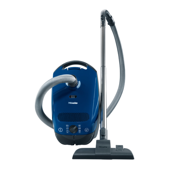
Miele S 2120 Технічна інформація - Сторінка 3
Переглянути онлайн або завантажити pdf Технічна інформація для Пилосос Miele S 2120. Miele S 2120 34 сторінки. Vacuum cleaners
Також для Miele S 2120: Брошура (12 сторінок), Інструкція з експлуатації Посібник з експлуатації (24 сторінок)

S2 Canister Vacuums
2.1
Accessories .................................................................................................. 32
3
Fault Repair .............................................................................................................. 32
3.1
Suction Power Too Low ................................................................................ 32
4
Service ...................................................................................................................... 33
4.1
Telescopic Suction Hose Locking Piece Replacement ................................. 33
4.2
Pushbutton Replacement (for Telescopic Hoses) ......................................... 34
List of Figures
Figure D-1: Control Panel (at Rear of Vacuum) ...................................................................... 7
Figure D-2: Internal Component Layout .................................................................................. 7
Figure D-3: External Component Layout (with Basic Suction Hose) ....................................... 8
Figure D-4: External Component Layout (with Electro Accessories) ....................................... 9
Figure 010-1: Support Roller and Axle .................................................................................. 11
Figure 010-2: Caster Removal .............................................................................................. 12
Figure 010-3: Electronic Retainer.......................................................................................... 12
Figure 010-4: Motor ............................................................................................................... 13
Figure 010-5: Cord Reel and Motor....................................................................................... 13
Figure 010-6: Cord Reel Retainer on Side ............................................................................ 14
Figure 010-7: Cord Reel, Unwound ....................................................................................... 14
Figure 010-8: Cord Reel Clamped to Reel Assembly Body .................................................. 15
Figure 010-9: Screws Securing Cord Reel ............................................................................ 15
Figure 010-10: Cord Reel Tabs ............................................................................................. 16
Figure 020-1: Bag Change Indicator ..................................................................................... 18
Figure 020-2: Filter Types ..................................................................................................... 19
Figure 020-3: Bag and Holder ............................................................................................... 19
Figure 020-4: Bag Change Indicator Removal ...................................................................... 20
Figure 020-5: Casing Top Removal ...................................................................................... 20
Figure 020-6: Filter Frame Retaining Tabs ........................................................................... 21
Figure 020-7: Cover Frame Screws ...................................................................................... 22
Figure 020-8: Cover Frame Removal .................................................................................... 22
Figure 020-9: Air Inlet Regulator ........................................................................................... 23
Figure 020-10: Changing the Bag ......................................................................................... 24
Figure 020-11: Replacing the Super Air Clean Filter ............................................................. 24
Figure 020-12: Replacing the Active Air Clean or Active HEPA Filter ................................... 25
Figure 020-13: Changing the Dust Compartment Filter ......................................................... 25
Figure 030-1: Rotary Selector Switch .................................................................................... 27
Figure 030-2: Cap Screws .................................................................................................... 29
Figure 030-3: Notches ........................................................................................................... 29
Figure 030-4: Tabs ................................................................................................................ 30
Figure 040-1: Accessories .................................................................................................... 32
Figure 040-2: Telescopic Locking Piece ............................................................................... 33
Figure 040-3: Pushbutton Replacement ................................................................................ 34
List of Tables
Table C-1: S2 Data Sheet, US Models .................................................................................... 6
3
