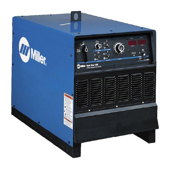
Miller 907363 Посібник користувача - Сторінка 26
Переглянути онлайн або завантажити pdf Посібник користувача для Зварювальна система Miller 907363. Miller 907363 48 сторінок. Ce and non-ce arc welding power source

4-12. Connecting Weld Output Cables
1
Tools Needed:
3/4 in. (19 mm)
!
Turn off power before connecting to
weld output terminals.
!
Failure to properly connect weld
cables may cause excessive heat
and start a fire, or damage your ma-
chine.
.
Do not place anything between weld
4-13. Remote 14 Receptacle Information
24 VOLTS AC
REMOTE OUTPUT CONTROL
115 VOLTS AC
GND
REMOTE POWER ON/OFF
REMOTE VOLTAGE SENSING
* Not Used
OM-222 Page 22
6
3
4
5
cable terminal and copper bar. Make
sure that the surfaces of the weld cable
terminal and copper bar are clean.
1
Correct Weld Cable Connection
2
Incorrect weld Cable Connection
3
Weld Output Terminal
4
Supplied Weld Output Terminal Nut
Socket
A
24 volts AC. Protected by supplementary protector CB2.
B
Contact closure to A completes 24 volts AC contactor control circuit.
C
Command reference; 0 to +10 volts DC.
D
Remote control circuit common.
E
0 to +10 volts DC input command signal from remote control.
F
Current feedback; 1 volt per 100 amperes.
H
Voltage feedback; 1 volt per 10 arc volts.
I
115 volts, 15 amperes, 60 Hz AC. Protected by supplementary protector CB1.
J
Contact closure to I completes 115 volts AC contactor control circuit.
K
Chassis common.
G
Circuit common for 24 and 115 volts AC circuits.
*
To remote On/Off switch.
*
*
Voltage sensing signal from Negative (-) weld output terminal.
*
Voltage sensing signal from Positive (+) weld output terminal.
2
5
Weld Cable Terminal
6
Copper Bar
Remove supplied nut from weld output ter-
minal. Slide weld cable terminal onto weld
output terminal and secure with nut so that
weld cable terminal is tight against copper
bar.
connecting weld output cables 3−2010
Information
803 778-B
