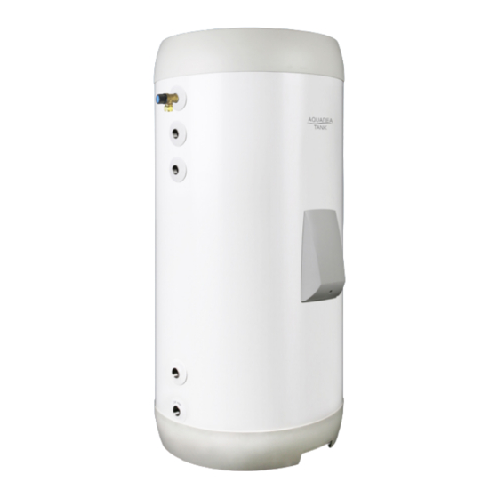
Aquarea 80341950 Посібник з монтажу, технічного та сервісного обслуговування - Сторінка 3
Переглянути онлайн або завантажити pdf Посібник з монтажу, технічного та сервісного обслуговування для Водонагрівач Aquarea 80341950. Aquarea 80341950 8 сторінок.

Pipe fitting and connections
Pipe fitting:
The piping must be fitted in accordance with the current
regulations in the area where the product is installed. All
pipe fitting must be performed by an authorized installer.
Pipe connections:
CW inlet: 3/4" BSP female
HW outlet: 3/4" BSP female
HW circulation: 3/4" BSP female
Coil flow/ret: 3/4" BSP female
T&P valve connection: 1/2" BSP female
Connection heights and dimensions, see next page.
It is recommended to install the product in a frost free
environment. The product must be installed in a room fitted
with a gulley. If this is not possible an overflow pipe (min.
ø18 mm internal) must be fitted to the P&T/safety valve. The
pipe must be installed uninterruptable and safe from frost,
sloping to a dimensioned gulley/drain.
The G3 valve kit is connected to the unit as shown in the
illustration.
Filling the unit
The unit MUST be filled with water before electric power
supply is turned on. Open main water supply. Drain air from
vessel through nearby hot water faucet until water flows
evenly. Close faucet.
Coil is filled when installing external heat source. Follow
instructions supplied with external heat source or contact
approved installer.
Draining
Turn off power supply. Turn off water supply. Drain unit by
disconnecting cold water inlet pipe. Open a nearby hot water
faucet to release vaccuum.
Draining the coil: See instructions supplied with external
heat source. Disconnect return pipe to empty coil.
Annual check-up
Perform first time after approx. 3 months in service, then
annually.
Check all pipe fittings for leaks. The function of the safety
valve must be tested by opening the valve and observing
that water flows freely. Close the valve after testing.
Check electrical connections for any damage. The internal
electric central is inspected by turning off the power supply,
then removing the el. box cover. Ensure that all internal
wiring and components are intact and working. Tighten wire
connection points. Fit the el. box cover before turning power
supply back on. If needed contact authorized personnel.
Service, maintenance and inspection
The manufacturer recommends that maintenance and
servicing of the unit is performed by authorized personnel in
accordance with the information in this manual.
The 5/4" element connection can be used for internal
inspection.
Spare parts
Product
Heating element
Thermostat
Element tool
El. box cover
Sensor
Description
RG 5/4" single tube with sensor pocket
TSR 00027 thermostat with sensor
KN 5/4" - for removing or fitting the element
Delta
Temperature sensor
Subject to changes without notice
G3 KIT
Exp.
vessel
CW
inlet
T&P valve
HW circ.
Coil
inlet
Tundish
Coil
outlet
1/2" Drain
elbow
Temperature sensor is supplied with
unit. Fit as shown (see also 'Electrical
installation').
3-way valve installation: See heat pump
installation manual.
3-way valve is not included. Must be
purchased separately.
HW outlet
Temp.
sensor
Prod. No.
71 234
80 314
801 51 95
75 086
81 809
3
