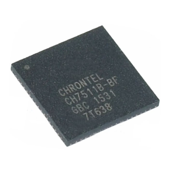
Chrontel CH7511B Посібник з проектування - Сторінка 3
Переглянути онлайн або завантажити pdf Посібник з проектування для Приймач Chrontel CH7511B. Chrontel CH7511B 16 сторінок. Edp/dp receiver

CHRONTEL
Note:
Pease make sure that the voltage of LVDD (VCC33) should be supplied before the voltage of DVDD
1.
and AVDD (VCC18).
The RESETB signal should be supplied to the CH7511B/7512B after the powers are stable.
2.
T1 (the VCC18 rise slope time) should not be larger than 2ms.
3.
4.
The exposed pad, which is the thermal pad, must be linked to GND.
All the Ferrite Beads described in this document are recommended to have an impedance of less than
5.
0.05Ω at DC; 23Ω at 25MHz & 47Ωat 100MHz. Refer to Fair Rite part #2743019447 for details (an
equivalent part can be used for the diagram).
2.2
Internal Reference Pins
• RBIAS pin
This pin sets the Band-gap Bias Voltage. A 10 KΩ, 1% tolerance resistor should be connected between RBIAS and
GND as shown in Figure 2. A smaller resistance will create less Band-gap Bias voltage. The distance between the
resistor and the CH7511B/CH7512B should be less than 6mm, the shorter and wider trace the better. For optimal
performance, this signal should not overlay the analog power or analog output signals.
2.3
General Control Pins
• RESETB
This pin is the chip reset pin for the CH7511B/7512B. The RESETB pin is internally pulled-up. But when it is
pulled-low, this pin places the device in the power-on-reset condition. As shown in Figure 3, one 10KΩ resistor is
necessary to be pulled high to DVDD (1.8V). One 0.1uf capacitor is recommended to be pulled low to GND. After
the powers are stable, send the RESETB signal (low to high) to the chip, as shown in Figure 1.
Option1: link the RESETB signal to the external GPIO_PCH signal (1.8V).
Option2: add the level shifter circuits to link the RESETB signal to the GPIO_PCH signal (3.3V).
• XI, XO
A 27MHz crystal (30ppm) can be connected to XI and XO as the CH7511B/7512B the optional reference clock
input. In PCB design, a 27MHz crystal must be placed as close as possible to the XI and XO pins, with traces
connected from point to point, overlaying the ground plane. Since the crystal generates the timing reference for the
CH7511B/7512B, it is essential that noise not couple into these input pins.
The crystal load capacitance, CL, is usually specified in the crystal spec from the vendor. Refer to Figure 3 for a
crystal circuit reference design and an example of load capacitors.
• REFCK
206-1000-014
Rev. 1.7
U1
68
RB IAS
QFN
CH 7511B
Figure 2: RBIAS Pin Connection
2020-07-14
R1
10K (1%)
AN-B014
3
