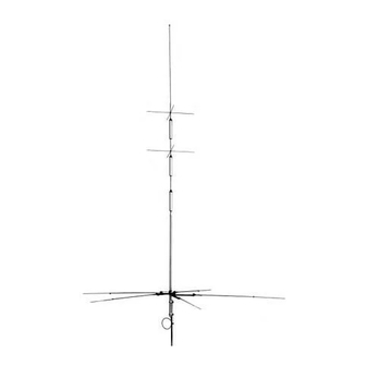
Diamond Antenna CP-6S Інструкція з експлуатації - Сторінка 3
Переглянути онлайн або завантажити pdf Інструкція з експлуатації для Антена Diamond Antenna CP-6S. Diamond Antenna CP-6S 4 сторінки. 80m, 40m, 20m, 15m, 10m and 6m (3.5, 7/14/21/28-29 and 50mhz) six-band vertical antenna

●Parts Description
Parts #
Description
15201A
Mast bracket set
15202
Mast support pipe
15203
Radial element holder
15204
Feed point assembly
15205
Pipe No. 1 φ30
15206
Double element trap
coil assembly
15207
Single element trap
coil assembly
15208
Pipe No. 2 10φ
15209
Capacity hat assembly
15210
6m(50MHz) radial element
trap coil assembly
15211
10m(28-29MHz) radial element
trap coil assembly
15212
15m(21MHz) radial element
trap coil assembly
15213
20m(14MHz) radial element
trap coil assembly
15214
40m(7MHz) radial element
trap coil assembly
15215
80m(3.5MHz) radial element
trap coil assembly
15216
Radial element
15217
Radial element
fastener ring
15218
Grip nut
15219
Hex head screw M6 x 8
15220
Spring washer M6
15221
Tapping screw M4 x 8
15222
Internal tooth lock
washer M4
15223
Capacity hat
fastener ring
15224
V-bolt with nut
15225
Insulating ring
15226
Cable with core
15227
Self-melting tape
<<Note>>
・ Fastening the radial element trap coil
assembly tightly may be damaged.
・ In the case of spread around style
radial elements,the turn to fix the
radials is not restricted. However, the
radials of the lower frequencies are
more influenced by the surrounding
condition. Set the radials for 80m and
40m as far away as possible from the
buildings.
・ In the case of the one direction style
radial elements, set the radial for 80m
and one the radial for 40m at the both
end.
(Refer to Fig-5)
Pull one piece of the radial element
holder down 2cm and fix it. (Fig-3)
2cm
・ In case of using the metallic stay wire,
set the wire on the lower mast bracket
set and attach the insulators at within
1m from the mast bracket set in order
to insulate.
・ It is possible to remove the radials you
don't use the band for.
●Spread around style radial elements
Qty
2
1
2
1
1
1
1
1
8
●One direction style radial elements
1
1
1
1
7MHz
1
●Assembly Instruction
1 Put radial element in each radial
1
element trap coil assembly by referring
6
to the typical element length listed in
Table A and fasten it with element
6
fastener ring. (Fig-6)
6
2 Screw radial nut (outside) of radial coil in
3
the depth of threaded portion lightly.
3
6
Radial element trap coil
6
2
2
2
1
1
Grip nut
※Don't screw this screw.
3 Connect pipe No.1, double element trap
coil assembly, single element trap coil
assembly and pope No.2 in the vertical
element section and fastening them
with tapping screws and inner tooth
washers by aligning holes in each joint
section.
4 Attach four capacity hat assemblies to
each capacity hat holder section.
Capacity hat holders are set at the
specified sections in the factory.
Locations
holders are fixed at about 24cm (9.4")
below the top end of single element
trap coil assembly for upper capacity
hat and about 24cm (3.1") below the
top end of double element trap coil
assembly
respectively. Though, upper and lower
capacity hat assemblies do not have to
(Fig-3)
be aligned electrically, it looks better if it
is aligned well. (Refer to Fig-7)
5 Attach mast support pipe to mast with
mast brackets. Mast support pipe's
tapping hole has to be placed above
the brackets and it has to be pointed
outside against the mast. Upper end of
mast support pipe has to be placed
(Fig-4)
3.5MHz
(Fig-5)
Radial element fastener ring
Adjustment length of each
radial element(Table-A)
(Fig-6)
for
those
capacity
hat
for
lower
capacity
hat
more than 12cm(4.7") above the top
end of the mast.
24cm
Single element trap
Double element trap
coil assembly
coil assembly
Applox. 12cm(4.7")
Coaxial cable
(not included)
Mast
Trapping hole
this side
Support pipe
Mast brackets
Spring washer
Mast
Support
V-bolt
pipe
6 Place two radial element holders from
upper end of the support pipe and
fasten temporary with screwdriver. Do
not fasten too tightly at this stage,
otherwise feedpoint assemblies might
not be put into the support mast later.
Radiator
Feed point assembly
Hex head screw
Grip nut
Screw
(2pcs/upper
& lower)
Align water drain hole
Hex head screw
downward when attach
Radial element holder
Mast support pipe
7 Connect cable with core to coaxial cable
with MP connector. After that, connect
a coaxial cable to feedpoint assemble
through the support pipe.
(Note) Be sure to do waterproofing with
self-melting tape and plastic tape.
8 Align the hole in the lower part of
feedpoint assembly with the hole in the
support pipe and secure them with hex
head screw (M6x8) and spring washer.
9 Place vertical element on feedpoint
assembly and fix with two hex head
screws (M6x8) and spring washers.
(2 places)
8cm
(Fig-7)
Cable with core
Nut
Mast bracket set
(Fig-8)
Radial element
(Fig-9)
