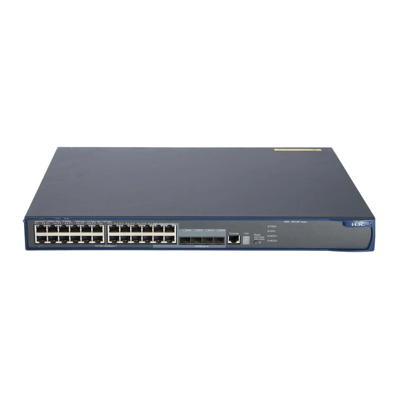
HP 5120-24G-PoE+ EI Посібник з конфігурації - Сторінка 19
Переглянути онлайн або завантажити pdf Посібник з конфігурації для Перемикач HP 5120-24G-PoE+ EI. HP 5120-24G-PoE+ EI 39 сторінок. Hp 5120 ei switch series
Також для HP 5120-24G-PoE+ EI: Технічний паспорт (17 сторінок)

To specify a priority for the switch:
Step
1.
Enter system view.
2.
Specify a priority for the
switch.
Connecting physical IRF ports
When you connect two neighboring IRF members, connect the physical ports of IRF-port 1 on one
member to the physical ports of IRF-port 2 on the other, as shown in
IMPORTANT:
No intermediate devices are allowed between neighboring members.
Figure 8 Connecting IRF physical ports
Connect the switches into a daisy chain topology or a ring topology, which is more reliable (see
9). In ring topology, the failure of one IRF link does not cause the IRF fabric to split as in daisy chain
topology. Rather, the IRF fabric changes to a daisy chain topology without interrupting network services.
Figure 9 Daisy chain topology versus ring topology
Master
IRF-Port1
Subordinate
IRF-Port1
Subordinate
Daisy chain
topology
Command
system-view
irf member member-id priority priority
IRF
IRF-Port2
IRF-Port2
Subordinate
Master
IRF-Port1
IRF
IRF-Port2
IRF-Port1
IRF-Port1
Ring topology
15
Remarks
N/A
The default IRF member priority
is 1.
Figure
8.
IRF-Port2
IRF-Port2
Subordinate
Figure
