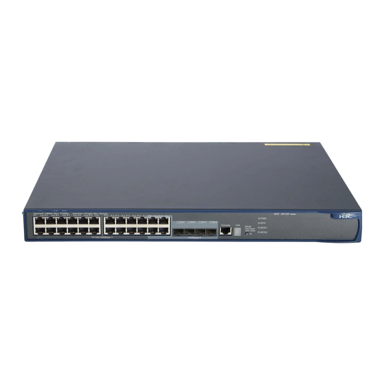
HP 5120-48G-PoE+ EI Посібник з конфігурації - Сторінка 11
Переглянути онлайн або завантажити pdf Посібник з конфігурації для Перемикач HP 5120-48G-PoE+ EI. HP 5120-48G-PoE+ EI 39 сторінок. Hp 5120 ei switch series
Також для HP 5120-48G-PoE+ EI: Технічний паспорт (17 сторінок)

For more information about configuration management, see Fundamentals Configuration Guide.
Loop-elimination mechanism
IRF has its own mechanism to eliminate loops, though loop control protocols such as the spanning tree
feature cannot be configured on IRF physical interfaces. Before an IRF member device forwards a packet,
it identifies whether loops exist on the forwarding path based on the source and destination physical
interfaces and the IRF topology. If a loop exists, the device discards the packet on the source interface of
the looped path. This loop-elimination mechanism will drop a large number of broadcast packets on the
IRF physical interfaces. To reduce the SNMP notifications of packet drops, do not monitor packet
forwarding for the IRF physical interfaces.
Master election
Master election is held each time the IRF fabric topology changes, for example, when the IRF fabric is
established, a new member device is plugged in, the master device fails or is removed, the IRF fabric
splits, or IRF fabrics merge.
Master election uses the following rules in descending order:
Current master, even if a new member has higher priority.
1.
When an IRF fabric is being formed, all member switches consider themselves as the master, and
this rule is skipped
Member with higher priority.
2.
Member with the longest system uptime.
3.
Member with the lowest bridge MAC address.
4.
The IRF fabric is formed on election of the master.
During an IRF merge, the switches of the IRF fabric that fails the master election must reboot to re-join the
IRF fabric that wins the election.
After a master election, all subordinate switches reboot with the configuration on the master. Their
configuration files do not take effect.
IRF multi-active detection
An IRF link failure causes an IRF fabric to split in two IRF fabrics operating with the same Layer 3
configurations, including the same IP address. To avoid IP address collision and network problems, IRF
uses multi-active detection (MAD) mechanisms to detect the presence of multiple identical IRF fabrics,
handle collisions, and recover from faults.
Multi-active handling procedure
The multi-active handling procedure includes detection, collision handling and failure recovery.
Detection
The MAD implementation of the switch detects active IRF fabrics with the same Layer 3 global
configuration by extending the LACP or gratuitous ARP protocol.
7
