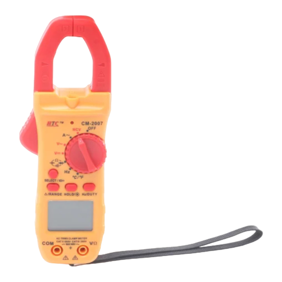
HTC CM-2007 Посібник - Сторінка 4
Переглянути онлайн або завантажити pdf Посібник для Вимірювальні прилади HTC CM-2007. HTC CM-2007 5 сторінок. Digital clamp meter

Do not use this NCV test function to judge the existence of
voltage.
2. The test result might be affected by many factors such as the
design of the socket and the thickness of insulation material.
3. The LED light might glow when user inputs voltage into the
meter terminal.
4. Flashlight or motor driver and other external sources may cause
disturbance and might cause the wrong results.
4.6 DIODE AND CONTINUITY TEST
4.6.1 Set the rotary switch to "
Ω
" range. The original state is
diode measurement mode.
4.6.2 Forward measurement: Connect red test lead to the
positive polarity and the black test lead to the cathode
polarity of the diode. LCD will display the approx. value
of forward voltage drop.
4.6.3 Backward measurement: connect red test lead to
the cathode polarity and the black test lead to positive polarity of the
diode. LCD will display "OL".
4.6.4 The complete diode testing includes forward and backward
measurement. If the result doesn't meet the descriptions above, it means
the diode is broken.
4.6.5 Press "SELECT" key to select the continuity measurement mode.
4.6.6 Insert the black test lead into "COM" terminal, and the red one
into "V/Ω" terminal.
4.6.7 Connect test leads to two points of tested circuit, if the resistance
is less than (50±10) Ω, the buzzer sounds.
Note:
DO NOT input any voltage value at this range!
1.
4.7 RESISTANCE MEASUREMENT
4.7.1 Set the rotary switch to "
Ω
" range and press "SELECT"
to swift to "Ω" range.
4.7.2 Insert the black lest lead into "COM" terminal and the red one
into "V/Ω" terminal.
4.7.3 Connect the test leads to the measured resistance
to get the measurement value (refer to picture 8).
Note:
1. Before measuring in line resistor, make sure that the
power is off and all capacitors have discharged
completely.
2. Do not apply any voltage at resistance range.
3. When input terminal is in open circuit, LCD will display "OL".
4. If there is an "OL" displayed on the LCD, it means it is over range,
switch to a higher range. When the test leads are shorted, there would
be about 1Ω stray resistance.
4.8 CAPACITANCE TEST
4.8.1 Set the rotary switch to "
Ω
" range and
press "SELECT" to swift to "
" range.
4.8.2 Insert the black test lead into "COM" terminal,
and the red one into "V/Ω" terminal (refer to picture
9).
4.8.3 Press "REL" key to clear the reading to make the LCD displayed
zero.
4.8.4 Connect the capacitor to "COM" and "V/Ω" terminal. (Note: the
red test leads is for positive pole +). LCD displays capacitance value.
Note:
1. Don't input voltage or current at Capacitance range.
2. In order to assure the accuracy, please press "REL" to clear the
reading before testing.
3. There is only the auto range mode under the capacitance range.
4. The capacitor must be completely discharged before testing.
5. The reading of 200uF range will take more than 15 seconds to be
stable.
4.9 FREQUENCY MEASUREMENT
4.9.1 Turn the function swift to Hz range. Insert the black lest lead in
"COM" terminal and the red one in "V/Ω"
terminal.
4.9.2 Connect the test leads to the measured
circuit and get the measurement value. (Refer to
picture 10)
Note:
1. In noisy environment, it's better to use shield
cable to measure a low signal.
2. When measuring high voltage circuit, do not touch the high voltage
circuit.
3. Don't input voltage higher than 250V RMS or it may damage the
meter.
4.10 TEMPERATURE TEST
4.10.1 Set the rotary switch to "℃" range.
4.1.12 Insert the black plug of the thermocouple
sensor into "COM" and red one into "V/Ω" jack,
and put the working terminal (temperature
measuring end) of thermocouple on the surface or
inside the object to be tested. Then you can read
temperature from the screen, and the data is in
Centigrade. (Refer to picture 11)
Note:
1. The meter should be far away high temperature. Use the
thermocouple probe within the specified temperature range.
2. Don't change the temperature probe randomly, or the accuracy will
not be guaranteed.
3. Don't input voltage at temperature range.
4.11 AUTO POWER OFF
4.11.1 The meter will auto power off if there is not any operation in 15
minutes and come into dormant mode. The beeper will sound five times
within 1 minute before power-off.
To restart the meter, please press any function key or turn to the
function swift.
4.11.2 Press "SELECT" key and turn on the meter or press "SELECT"
when the meter is in dormant mode to wake up the meter and the
"AUTO POWER OFF" function will be cancelled
5. MAINTENANCE
The meter is a precise instrument. Random changes to the circuit should
be avoided.
Note:
1. When the LCD displays "
", please exchange the battery in time.
2. Before replacing battery or fuse, please remove the test leads from
the measuring point and turn off the power.
3. Keep the meter away from water, dust and shock.
4. DO NOT use the meter under high temperature, high humidity,
combustible, explosive and strong magnetic environments.
5. Clean the case of the meter regularly with cleaner. DO NOT use
corrosive solvents, combustible, explosive and strong magnetic
environments.
