EPC 9115 Посібник із швидкого старту - Сторінка 2
Переглянути онлайн або завантажити pdf Посібник із швидкого старту для Материнська плата EPC 9115. EPC 9115 9 сторінок.
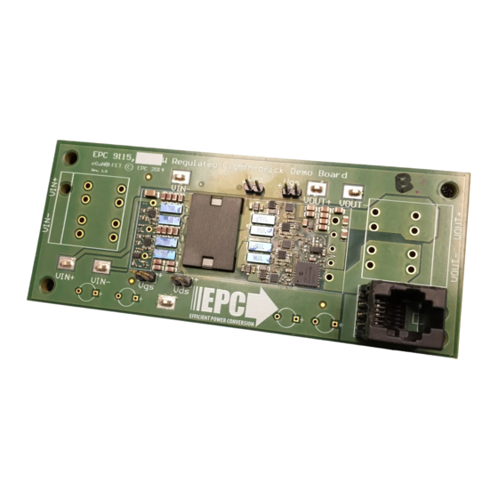
QUICK START GUIDE
QUICK START PROCEDURE
Demonstration board EPC9115 is easy to set up to evaluate the
performance of the EPC2020 and EPC2021 eGaN FETs and LM5113 and
UCC27611 drivers. Refer to Figure 2 for proper connect and measurement
setup and follow the procedure below:
1. With power off, connect the input power supply bus between
V
+ and V
- euro connectors as shown.
IN
IN
2. Add input and output voltage measurements to the Kelvin
connections provided as shown.
3. With power off, connect the load as desired between V
euro connectors as shown. A resistive or constant current load is
recommended.
4. Turn on the supply voltage to the required value. Do not exceed the
absolute maximum voltage of 60 V on V
5. Measure the output voltage to make sure the board is fully functional
and operating no-load.
Lf2 330n
V_IN+
Cf1
12*1 uF
Q1
EPC2021
p1
V_IN-
Q2
EPC2021
p2
V_BIAS_PRI
V_BIAS_SEC
EPC – EFFICIENT POWER CONVERSION CORPORATION |
+ and V
OUT
.
IN
Q3
EPC2021
p2
1T
vp+
4T
vp-
1T
Q4
EPC2021
p1
s1
Figure 1: Block Diagram of EPC9115 Demonstration Board
WWW.EPC-CO.COM
6. Turn on active load and adjust to the desired load current while staying
below the maximum current (This will depend on the cooling provided.
If no forced air cooling, then keep the load current below 5 A).
7. If testing under moderate to full load conditions, ensure that a fan
or other source of forced convection is producing adequate airflow
(≥ 400 LFM recommended for full load operation).
8. Once operational, adjust the bus voltage and load current within the
allowed operating range and observe the output switching behavior,
efficiency and other parameters.
-
OUT
9. For shutdown, please follow steps in reverse.
NOTE. For accurate high frequency content switch node and gate voltage waveforms,
use a short ground clip or purpose-made probe adapter, as shown in Fig. 3. Avoid long
ground leads on oscilloscope probes. Please note that primary and secondary side
grounds are not connected to each other on the EPC9115 demo board. When
measuring multiple signals ensure that they are always referenced to the same 'ground'
potential to avoid potential circuit failure or instrumentation failure.
vsa
vsct
vsb
Q5
Q7
EPC2020
EPC2020
Q6
Q8
EPC2020
EPC2020
s2
Controller
V_OUT_SNS
I_OUT_SNS
| COPYRIGHT 2015 |
Lf1 470nH
R2
D4
5.2k
vsa
D5
vsb
M1
M2
D1
C2
470nF
A1
p1
A2
p2
s1
s2
snb1
snb2
EPC9115
V_OUT+
C1
100n
Cf
12*4.7 uF
V_OUT-
| PAGE 2