EPH Controls DETACH PRO B1PF Інструкція з монтажу та експлуатації - Сторінка 2
Переглянути онлайн або завантажити pdf Інструкція з монтажу та експлуатації для Контролер EPH Controls DETACH PRO B1PF. EPH Controls DETACH PRO B1PF 4 сторінки. 3 port motorised valve actuator

INSTALLATION & OPERATING INSTRUCTIONS
1. Valve positioning
Install the valve so the actuator head is not below the horizontal level of the pipework. The open vent and
cold feed must not be isolated. The flow must be in the direction of the arrow. (from the centre port to either
Port A or Port B).
2. Fitting the valve body to the pipework
Fit the valve body using the nuts and olives provided. When tightening the compression nuts ensure that
only the valve body is used for grip. Take care not to overtighten.
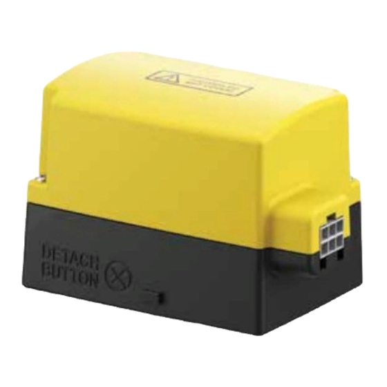
3. Removal of actuator from the valve body
To remove the actuator head from the valve body ensure that the manual override lever is in the manual
position. Remove the two screws that fix the actuator cover to the base. Remove the actuator cover. Remove
the two screws that fix the base to the valve body. Remove the base of the actuator.
4. Fitting of actuator to the valve body
Before fitting the actuator, please ensure that the maual override lever is in the raised manual position and
the fixing screw is loosened. The actuator is mounted by aligning the 4mm flat spindle on the valve body to
the identically sized slot on the actuator. Tighten the two fixing screws on the base of the actuator. Fit the
actuator cover and tighten the two screws to hold the cover in place.
Once the valve is fitted, place the manual override lever in the raised manual position. It is now possible
to flush and drain the system to remove any foreign matter. The system can now be refilled and corrosion
inhibitor may be added if required.
5. Wiring Connections
5.1 The 1.2 metre cable can be connectd as follows:
WIRE COLOUR
Blue
Orange
Grey
White
Yellow / Green
CAUTION!
Ensure that no more than a 3A fuse is used to supply all controls.
It is not permissible to use any voltage other than 230V on the auxiliary switch.
Electrical installation must conform with current I.E.E. regulations.
Neutral supply
Hot Water ON from cylinder stat or ON from programmer
Also connect to boiler and pump live.
Hot Water OFF from cylinder stat or OFF from programmer
Central Heating ON from room stat or ON from programmer
Earth connection
DESCRIPTION
Page 2
