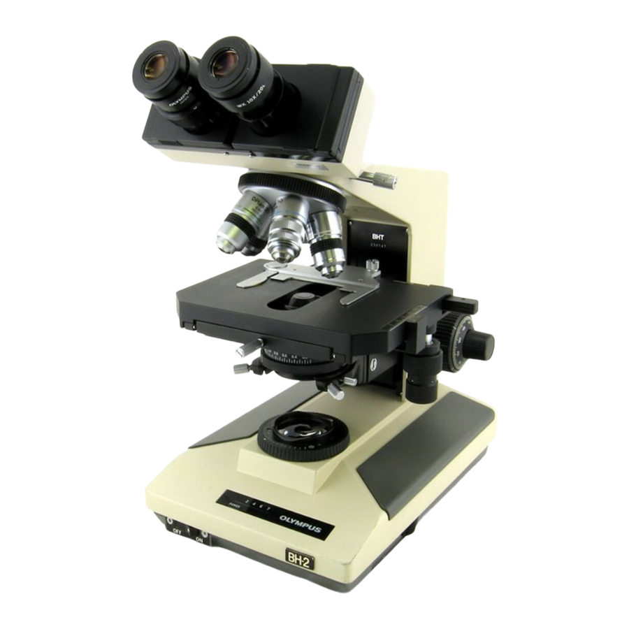
Olympus BH2 Series Повний демонтаж, очищення та повторний монтаж - Сторінка 16
Переглянути онлайн або завантажити pdf Повний демонтаж, очищення та повторний монтаж для Мікроскоп Olympus BH2 Series. Olympus BH2 Series 40 сторінок. Phase contrast
Також для Olympus BH2 Series: Посібник з усунення несправностей та налаштування (46 сторінок), Повний демонтаж, очищення та повторний монтаж (23 сторінок), Демонтаж, очищення та повторний монтаж (45 сторінок), Посібник (6 сторінок), Посібник з монтажу (9 сторінок)

the painted finish of the pillar arm while cleaning the
grease from the part. The details of removal of the
threaded lock ring are included here for the sake of
completeness.
To remove the threaded lock ring from the pillar arm,
apply heat with a heat gun to soften the adhesive
staking the three flat-head M3X6 screws securing the
threaded lock ring to the pillar arm casting. After the
screws have been thoroughly heated, place the tip of a
suitable JIS screwdriver into the heads of the three
screws and smack the screwdriver handle with a soft-
faced mallet, for luck. Then loosen and remove the
three flat-head screws (see
threaded lock ring and pull it straight out to remove it
from the brass pinion mount (see
Figure 31 – Remove screws holding the threaded lock ring
Figure 32 – Remove threaded lock ring from pillar arm
Disassemble the Fine-Focus Gear Cluster
The fine-focus gear cluster consists of three drive gears
located within the right-hand coarse-focus knob. These
gears, which are sandwiched between the aluminum
gear-support base and the brass gear-retaining ring (see
Figure
33), are driven by the small pinion gear that is
pressed into the underside of the right-hand fine-focus
knob (see
Figure
16).
Complete Teardown, Cleaning, and Reassembly of the Olympus BH-2 Coaxial Focus Mechanism
Figure
31).
Grasp the
Figure
32).
Figure 33 – The fine-focus gear cluster
Use a suitable JIS screwdriver to remove the two
M2.6X6 flat-head countersink screws (on the left and
right sides) and the single M2.6X5 pan-head screw (in
the middle) holding the brass gear-retaining ring in
position (see
Figure
34).
Figure 34 – Remove screws holding gear-retaining ring
Remove the brass gear-retaining ring that is holding the
three drive gears in the gear cluster in place (see
35).
Figure 35 – Remove the brass gear-retaining ring
Figure
Revision 4
Page 16 of 40
