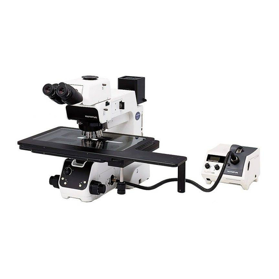
Olympus MX61L Посібник з монтажу - Сторінка 41
Переглянути онлайн або завантажити pdf Посібник з монтажу для Мікроскоп Olympus MX61L. Olympus MX61L 49 сторінок. 200mm/300mm compatible semiconductor/fpd inspection microscopes

EXTERNAL CONTROL OF REVOLVING NOSEPIECE
1
Connector Used
HR212-10R-8SDL (HIROSE ELECTRIC)
Applicable plug examples
Straight type: HR212-10P8PSAT
Right-angle type: HR212-10LA8PSAT
2
Pin Layout and Signal Names
All of the input/output signals are at the TTL level. The pin layout is shown on each connector.
No.
1
2
3
4
5
6
7
8
3
Control Specifications
The revolving nosepiece starts rotation when MOVE-R or MOVE-L is set to "L". As the chattering processing is used for
signal detection, the retention period of "L" should be at least 0.1 [s]. Since the "L" signal is not accepted during rotation, it
is required to set the signal to "H" temporarily and then switch it again to "L" when successive drive is necessary. In this
processing, the interval from the rise "L
Since the MOVE signal is "L" during operation, it is recommended to send the signal in synchronism with the MOVE
signal when successive drive is necessary.
4
Revolving Nosepiece Position Numbers (Index Nos. on the Center of Revolving Nosepiece)
Table 2 shows the relationship between the revolving nosepiece position numbers and the STY signals.
Table 1 Signal Names
Signal Name
I/O
MOVE-R
I
GND
–
MOVE-L
I
+5VD
–
MOVE
O
STY0
O
STY1
O
STY2
O
H" till the fall "H
Table 2 Revolving Nosepiece Position Numbers
Position No.
STY2
1
2
3
4
5
During rotation
Description
Nosepiece leftward switching request signal
GND
Nosepiece rightward switching request signal
+5 VD
"Rotating" (Out of light path) signal
Nosepiece position No. signal 0
Nosepiece position No. signal 1
Nosepiece position No. signal 2
L" should be at least 1.2 [s].
STY1
1
1
1
0
1
0
0
1
0
1
1
1
MX61/MX61L
– : Negative logic.
STY0
0
1
0
1
0
1
38
