Axminster C0 Інструкція з експлуатації - Сторінка 4
Переглянути онлайн або завантажити pdf Інструкція з експлуатації для Токарний верстат. Axminster C0. Axminster C0 14 сторінок. Mode engineer series metal turning lathe

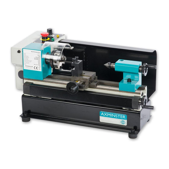
1. THE HEADSTOCK
The motor provides a direct drive to the spindle via an internal tooth type belt. Spindle speed is
variable, and is regulated by the Speed Control Knob(4). Located on the main control panel.
The 3-jaw self centering chuck(8) is mounted on the spindle flange. To remove the chuck, simply
remove the three securing nuts to rear of the flange allowing it to be pulled free together with
three mounting studs.
Note: The Chuck has a protection cover(7). Opening the cover, main power of the lathe will
be switched off, so keep closing the cover while running.
2. THE TAILSTOCK
The Tailstock Casting(11), may be moved along the bed to any desired position and is secured in
position by force of two screw (Front of the tailstock,) to lock or loose the wedge of the tailstock,
then you can remove or fix the tailstock casting.
3. THE SADDLE AND THE CROSS-SLIDE
The saddle carries the Cross-Slide, on to which is mounted the Tool Rest(10) allowing intricate
and delicate operations to be performed. It may be driven by a leadscrew, Via a Drive Nut, to
provide automatic feed when the Clutch(1) at the right position, is operated.
UNPACKING & PREPARING FOR USE
On receipt, carefully unpack the lathe, inspect to ensure that not damage was suffered in transit
and all parts are accounted for. Should any damage be apparent, or parts are missing, please
contact your dealer immediately.
With assistance, considering the weight of machine, raise it on to a good solid surface or
workbench. Proceed to remove all traces of preservative with paraffin or good quality solvent, and
lightly oil all machined surfaces.
Saddle, cross-slide and compound slide adjustments are all factory set to ensure smooth
movement in both directions. If however the adjustments have been upset during transit,
indicated by stiff or erratic movement, refer to 'settings and adjustments' for the methods of
adjustment.
All hex. Keys and spanners necessary to carry out various adjustments are supplied, together
with a chuck key for the 3-jaw chuck and a spare fuse. The fuse holder is located on the main
control panel.
The three external jaws for the 3-jaw self centering chuck. Extend the capacity of the chuck and
are discussed in greater detail under "Accessories".
MOUNTING THE MACHINE
The machine should be mounted on a workbench, of sufficient height so that you do not need to bend
your back to perform normal operations.
Ensure the location is adequately lit and that youwill not be working in your own shadow.
STARTING PROCEDURE
A. DURING INSTALLATION-INITIAL START.
First put the lathe plug in the socket then release the Emergency Stop Switch (3), the power
lamp(5) lights.
4
