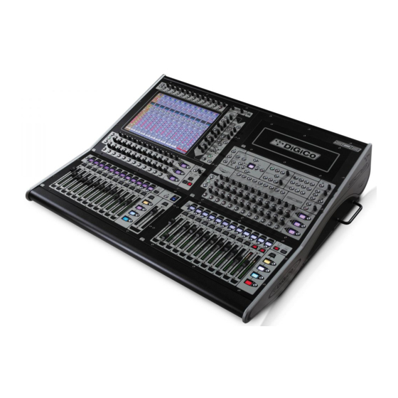
digico SD8 Інструкції з техніки безпеки, інструкція з налаштування та встановлення - Сторінка 13
Переглянути онлайн або завантажити pdf Інструкції з техніки безпеки, інструкція з налаштування та встановлення для Музичний мікшер digico SD8. digico SD8 13 сторінок. Replacing and cleaning faders
Також для digico SD8: Посібник (9 сторінок)

Typical optical cable breaks do not have the cable broken right through and it may look OK externally. Typical causes of optical
cable breakage are being run over by a wheel in a rail (such a sliding doors used in loading bays) or by trapping in heavy tight
fitting door, such as used in recording studios. Very tight bends caused by pulling a cable very tight with a knot tied in it can also
cause the light pipe to break.
It should be noted that the optical cable is not repairable on site. It is best considered that it is not repairable at all, and treated with
due care. In general it is not considered economic to repair broken optical cables.
Repair and making of these cables is a highly skilled job requiring specialised tools and materials. Because the lenses are bonded
with an optical glue, the internal parts of connectors cannot be re-used. It is not possible to "splice" broken cable sections without
using a connector to terminate the broken ends of the glass strands. The usual fix for a break near a cable end is to shorten the
cable past the break and fit a new plug. A break in the middle leads to 2 cables half the length with 2 new plugs or just scrapping
the cable.
See DiGiCo Technical Bulletin (TB99) for Optical Fault Finding Notes.
Checking the Optical cables ........................................................
Note that the data transmission system uses IR laser light sources and is scattered light system. This means the data signal
cannot be seen, unlike Toslink cables used for CD players for example. This means looking at cable connected to a live source will
not show if the signal is getting through. As with all laser sources users should not look directly into the end of cable with the
other end connected
To test the integrity of a HMA cable, use a regular light source (torch/flashlight or table light) at one end and see if the light
emerges from both lenses at the other end. Because the cables uses lenses, this will normally appear as the light is quite distant
down a tunnel. Which in a way it is!
Setting Up External Display Monitors .........................................
The Mixer is provided with an output for an external PC monitor. This is a standard SVGA analogue 15 pin HD D connector. The
screen is the system overview screen. This a special purpose screen, set up from the mixer system to display information useful
to the operator.
Most operators will wish to connect a monitor to the overview output. Typically this is set up to show the operation of all input
channels simultaneously, which cannot be seen continuously on the mixer itself.
Connecting an external screen ....................................................
The overview output has adjustable resolution. This is shipped set to 1024 x 760 as this suits the majority of modern monitors for
"plug-in and go" use. This offers the possibility to display more information, including all 96 input channels.
However it is recommended that, if available, a 1280 x 1024 XVGA monitor is used to allow the maximum capabilities of the
overview to be used.
The change the resolution requires changes to internal set up files of the embedded control computer and this should only be done
by a technician familiar with PC software set-up operations. See setup notes following.
Note the screen must be connected and powered at the same time or before the mixer is booted, for this screen to operate.
Note about LCD Monitors. ............................................................
In Digico's experience, if a modern LCD monitor (as opposed to conventional CRT based units) is used at a resolution below its
specified design figure, this may actually prove not to work correctly. Typical problems are poor vertical edge definition and
shimmering of the picture. This does not usually affect CRT screens run below maximum resolution. There is no adjustment in the
mixer to correct this, and the only solution is to try a different screen. This may be relevant in touring systems where operators may wish to
borrow a monitor. Note there is specific wide screen output setup available.
Important Note for Installers ........................................................
SD is product of considerable complexity and is subject to constant revision and changes to improve performance
and the manufacturing process.
As a result, the product as delivered may vary in small ways from the details in this manual. Any specification which is critical for
a user's application should be confirmed with Digico at the time of ordering. If there is the slightest question that might significantly
affect the installation of the SD8 in its new home, please ask!
Possible examples include critical dimensions with respect to custom-made furniture and fitments, or fitting details in relation to a
vehicle in mobile studio applications.
Paint Finishes & Colours .............................................................
For the purposes of matching furniture and other surrounding equipment in a permanent installation, the following paint specifications are
used in the SD8.
The Worksurface Panels and End Cheeks, rack face panels are painted using metallic "sparkle' effect gold, over this black highlights
are paited.
The Chassis Frame and Armrest are painted in a black paint, using a deep spatter finish coat.
Page 13
