ABB PME120-AN Інструкція з експлуатації - Сторінка 4
Переглянути онлайн або завантажити pdf Інструкція з експлуатації для Контролер ABB PME120-AN. ABB PME120-AN 18 сторінок. Electrical part-turn actuator

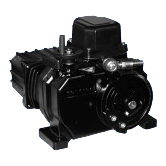
5. Assemblies
6
5
Table 1: PME 120
5.1 Operating mode
5.1.1 Normal mode
The motor triggered by the power electronics drives the output shaft (9) via oil-lubricated spur gears.
The drive lever mounted on the shaft transmits rotary motion to the valve.
The brake built in the motor (5) acts as a retainer when the power is off.
5.1.2 Handwheel mode
- Allows you to move the actuator manually when the electrical power is off.
- Turn the lock lever (4) clockwise
- Turn the handwheel (7) to move the lever to the wanted position.
- Release the lock lever.
The friction clutch is designed such that a handwheel force of around 11 N suffices to create the rated
torque on the actuator. If you should feel a considerable counter-force when moving the actuator by
hand, do not increase the force you apply to the handwheel. Otherwise, you might damage the actuator
or valve.
6. Technical Data
Rated torque [Nm]
Starting torque [Nm]
Rated speed [°/s]
Weight
Ambient temperature
Associated electronic unit
Power supply
(on electronic unit)
Max. power consumption with
115 / 230 V AC [A]
Current consumption in positioning
mode:
Table 2:
1)
actuator is equipped with additional electrical heater
4
7
4
3
8
10
1
9
2
(d0036rxa)
PME 120 AI
appr. 1.2 x rated torque (break-away torque in end positions 2
x rated torque for short time)
approx. 45 kg
(-25) 1) -10 ... +55°C
integrated in actuator
115 V AC (94 V ... 130 V) or 230 V AC
(190 V ... 260 V); 47.5 ... 63 Hz
approx. 40 ... 50% of I
1: Lever
2: Mechanical stops
3: Gearbox
4: Lock lever
5. Motor
6. Cover
(incl. electronics
for PME 120 AI)
7. Handwheel
8. Connector
9. Ouput shaft
10.Ball-and-socket joint
PME 120 AN
40 ... 100
1.5 ... 4.5
approx. 32 kg
(-25) 1) -10 ... +65°C
for field mounting: EAN 820
for rack mounting: EAS 822
1.0 / 0.5
., each
max
