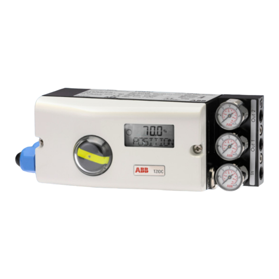
ABB TZIDC Посібник - Сторінка 5
Переглянути онлайн або завантажити pdf Посібник для Контролер ABB TZIDC. ABB TZIDC 8 сторінок. Digital positioner
Також для ABB TZIDC: Швидкий старт (2 сторінок), Швидкий старт (3 сторінок), Інструкція з експлуатації Посібник з експлуатації (10 сторінок), Інструкція з експлуатації (4 сторінок), Інструкція з введення в експлуатацію (2 сторінок)

TZIDC, TZIDC-200 DIGITAL POSITIONER | TD/TZIDC/TZIDC-200/NON-CONTACT_SENSOR-EN REV. A
Manual configuration of the parameters
Note
For detailed information on the parameterization, consult the
separate configuration and parameterization instructions
"COI/TZIDC/TZIDC-200".
The following parameters must be configured:
Parameter
Description
Selection of actuator type
•
ROTARY: Part-turn actuator
•
LINEARY: Linear actuator
Operating range end position minimum
Operating range end position maximum
Rotational direction of the spring effect or
rotational direction at OUT2 under pressure.
•
CLOCKWISE: Rotational direction clockwise
•
CTCLOCKWISE: Rotational direction
counterclockwise
Rotational direction to reach 0% position of the
actuator.
•
CLOCKWISE: Rotational direction clockwise
•
CTCLOCKWISE: Rotational direction
counterclockwise
NOTICE
Damage of actuators / valves or impairment of the regulator
function
In cases of incorrect parameterization, in particular of
parameter P6.3 (SPRNG_Y2) and P6.7 (ZERO_POS), damage to
actuators/valves or an impairment of the regulator function
may occur.
•
Ensure that the configuration of parameters is performed
in accordance with the following method.
Procedure
1. Activate the safety position via parameter P11.0 (FAIL_POS).
2. Reset the positioner via parameter P11.1 (FACT_SET) to the
factory setting.
3. Save the changes via parameter P11.5 (EXIT) in the non-
volatile memory.
4. Select the actuator type via parameter P6.2 (ACTUATOR).
•
ROTARY: Rotary actuator or gear rack actuator.
•
LINEARY: Linear actuator
5. Select parameter P6.0 (MIN_VR).
•
Move the actuator by pressing the button to the 0%
position (OUT1 depressurized).
•
Press and hold the ENTER button until the countdown is
finished (MIN_SET). The position is copied as MIN_VR.
Briefly press the ENTER button. The set limit value is
•
displayed for 2 seconds (MIN_SAVE).
•
Note the rotational direction
(clockwise/counterclockwise) of the actuator and
whether the actuator rotates into the 0% direction
(yes/no).
6. Select parameter P6.1 (MAX_VR).
•
Move the actuator by pressing the button to the 100%
position (OUT2 depressurized).
•
Press and hold the ENTER button until the countdown is
finished (MAX_SET). The position is copied as MAX_VR.
•
Briefly press the ENTER button. The set limit value is
displayed for 2 seconds (MAX_SAVE).
7. Select parameter P6.7(ZERO_POS).
•
If the actuator is moved into the 0% position when
configuring P6.0 (MIN_VR), position the parameter in the
relevant rotational direction (CLOCKWISE /
CTCLOCKWISE).
8. Select parameter P6.3(SPRNG_Y2).
•
Now position the parameter in the rotational direction
determined during the configuration of P6.0 (MIN_VR)
(CLOCKWISE / CTCLOCKWISE).
9. Select parameter P6.8 (EXIT) to return to the operational
level.
•
Select NV_SAVE to save the configurations in the non-
volatile memory.
•
Select CANCEL to reject the configurations in the non-
volatile memory.
10. Check the activation of the actuator. If the control behavior is
incorrect, check the parameterization in accordance with
these instructions and perform it again if required.
5
