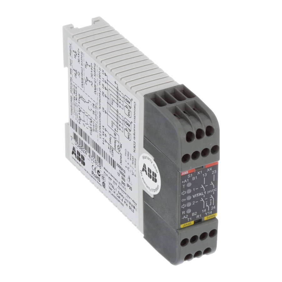
ABB vital 1 Оригінальна інструкція з експлуатації - Сторінка 6
Переглянути онлайн або завантажити pdf Оригінальна інструкція з експлуатації для Контролер ABB vital 1. ABB vital 1 20 сторінок. Safety controller
Також для ABB vital 1: Посібник (14 сторінок)

Function description
The safety is based on a dynamic safety circuit, using a single dynamic safety signal that is both generated and
monitored within Vital 1. The function is described in three steps:
1. The dynamic safety signal is generated in the safety module and is transmitted to the first safety sensor
through terminal T1 (transmitter).
2. All the safety sensors in the safety circuit are connected in series, i.e. the output signal from the first sensor
is connected to the input of the next sensor. This procedure is repeated up to the last safety sensor, where
instead the output signal is connected back to terminal R1 (receiver) on the safety module, closing the
circuit.
Every time the dynamic signal passes through a safety sensor (or adapter unit if the safety sensor is not
designed for the dynamic safety circuit) and the sensor is not interrupted, the signal is inverted. If the
sensor is interrupted the dynamic signal will be interrupted and a static "low" signal (0 VDC) will be set as
output from the sensor.
3. The dynamic safety signal connected back to R1 is monitored by the safety module. The safety relies on
each of the sensors (or adapter units) to invert the signal and pass it through to the next sensor as long as
the protection is not interrupted (e.g. when a safety switch is opened or a light beam crossed).
Depending on the number of sensors in the safety circuit, the signal will be inverted an even or odd number
of times when received and evaluated back at R1. Therefore, terminal S1 must be connected to B1 (+24
VDC) if an even number of sensors are connected to the dynamic safety circuit, making the safety module
expect the dynamic safety signal to be inverted an even amount of times when the safety system is not
interrupted. If an odd number of sensors are connected to the dynamic safety circuit, S1 must be
disconnected.
The safety module will activate its safety outputs when the input at R1 is OK (correct dynamic signal, safety circuit
"closed") and when the module is reset (option for manual or automatic reset). If a safety sensor is interrupted, the
dynamic signal will be interrupted and the safety module will deactivate the safety outputs. A short circuit over a
safety sensor will also be detected as the dynamic signal will not be inverted as expected, making the safety
module deactivate the safety outputs.
Vital 1 with an even number of sensors connected in series between T1 and R1. S1 connected to B1.
Vital 1 with an odd number of sensors connected in series between T1 and R1. S1 disconnected.
2TLC172156M0201, rev. C
2016-07-04
6
www.abb.com/jokabsafety
