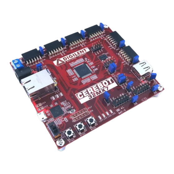
Digilent Cerebot 32MX7 Довідковий посібник - Сторінка 5
Переглянути онлайн або завантажити pdf Довідковий посібник для Материнська плата Digilent Cerebot 32MX7. Digilent Cerebot 32MX7 18 сторінок.

Cerebot 32MX7 Reference Manual
block in the "A" position when using the
standard USB type A (host) Connector, J20.
Place the shorting block in the "MICRO"
position for use with the USB micro-AB (OTG)
connector, J19.
When operating as a USB host, the
PIC32MX795 microcontroller controls
application of power to the connected device
via the VBUSON control pin (labeled
P32_VBUSON in the schematic). Bus power
is applied to the device by driving the VBUSON
pin high. Power is removed from the device by
driving the VBUSON pin low. The VBUSON
pin is accessed via bit 3 of the U1OTGCON
register.
The VBUSON pin drives the enable input of a
TPS2051B Current-Limited Power Distribution
Switch to control the application of USB power
to the host connector. This switch has over-
current detection capability and provides an
over-current fault indication by pulling the
signal P32_USBOC low. The over-current
output pin can be monitored via the INT1/RE8
pin on the PIC32MX795 microcontroller.
Details about the operation of the TPS2051B
can be obtained from the data sheet available
at the Texas Instruments web site.
There are reference designs available on the
Microchip web site demonstrating both device
and host operation of PIC32 microcontrollers.
These reference designs are suitable to use for
developing USB firmware for the Cerebot
32MX7 board.
Ethernet Interface
The Cerebot 32MX7 provides the ability to
interface with 10Mbps or 100Mbps Ethernet
networks. The PIC32MX795 microcontroller
contains a 10/100 Ethernet Medium Access
Controller (MAC). External to the
microcontroller, the Cerebot 32MX7 board
provides an SMSC LAN8720 Ethernet Physical
Layer Transceiver (PHY). Together, the MAC
and PHY provide a standard 10/100 Ethernet
interface.
www.digilentinc.com
Copyright Digilent, Inc. All rights reserved. Other product and company names mentioned may be trademarks of their respective owners.
The RJ45 connector J11, provides the physical
connection to an Ethernet network using a
standard Ethernet cable.
All devices on an Ethernet network must have
a unique address. This address is used to
direct packets on the network to a specific
device and to identify the device that originated
a packet. An Ethernet MAC uses a 48-bit
address value, commonly called the „MAC
Address‟. These address values are globally
unique to ensure that no two devices on a
network can have conflicting addresses. MAC
addresses are assigned by the IEEE. The
address to use with the Cerebot 32MX7 is
printed on a sticker attached to the bottom of
the board. The address is a twelve digit
hexadecimal number of the form:
00183Exxxxxx, where xxxxxx represents six
hexadecimal digits. This value is used to
initialize the Ethernet Controller MAC Station
Address registers in the Ethernet controller of
the PIC32MX795 microcontroller.
In order to connect to and operate with an
Ethernet network, the PIC32 microcontroller
must be running network protocol stack
firmware. Normally, the TCP/IP (Transmission
Control Protocol/Internet Protocol) network
protocol is used and "TCP/IP Stack" software
must be used. The Microchip Applications
Library, available for download from the
Microchip web site provides full protocol stack
support compatible with the PIC32MX795 MAC
and the LAN8720 PHY. Microchip also
provides numerous example programs
illustrating the use of their network protocol
stack for various applications.
When not using the Microchip network protocol
stack, refer to the manufacturer documentation
for the PIC32MX795 and LAN8720, plus
network protocol documentation, for operation
of the Ethernet interface.
The PIC32MX795 microcontroller provides two
alternate sets of pins that can be used to
connect the MAC to the external PHY. It also
provides two alternate standard MAC/PHY
interface signaling conventions. The Cerebot
32MX7 is designed to use the standard (not
page 5 of 17
