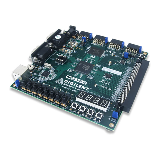
Digilent Nexys2 Довідковий посібник - Сторінка 5
Переглянути онлайн або завантажити pdf Довідковий посібник для Материнська плата Digilent Nexys2. Digilent Nexys2 18 сторінок.

Digilent
Nexys2 Reference Manual
www.digilentinc.com
series resistor for protection against short circuits (a short circuit would occur if an FPGA pin assigned
to a pushbutton or slide switch was inadvertently defined as an output).
Figure 8: Nexys2 I/O devices and circuits
Outputs: LEDs
Eight LEDs are provided for circuit outputs. LED anodes are driven from the FPGA via 390-ohm
resistors, so a logic '1' output will illuminate them with 3-4ma of drive current. A ninth LED is provided
as a power-on LED, and a tenth LED indicates FPGA programming status. Note that LEDs 4-7 have
different pin assignments due to pinout differences between the -500 and the -1200 die.
Outputs: Seven-Segment Display
The Nexys2 board contains a four-digit common anode seven-segment LED display. Each of the four
digits is composed of seven segments arranged in a "figure 8" pattern, with an LED embedded in
each segment. Segment LEDs can be individually illuminated, so any one of 128 patterns can be
displayed on a digit by illuminating certain LED segments and leaving the others dark. Of these 128
possible patterns, the ten corresponding to the decimal digits are the most useful.
Copyright Digilent, Inc.
Page 5/17
Doc: 502-134
