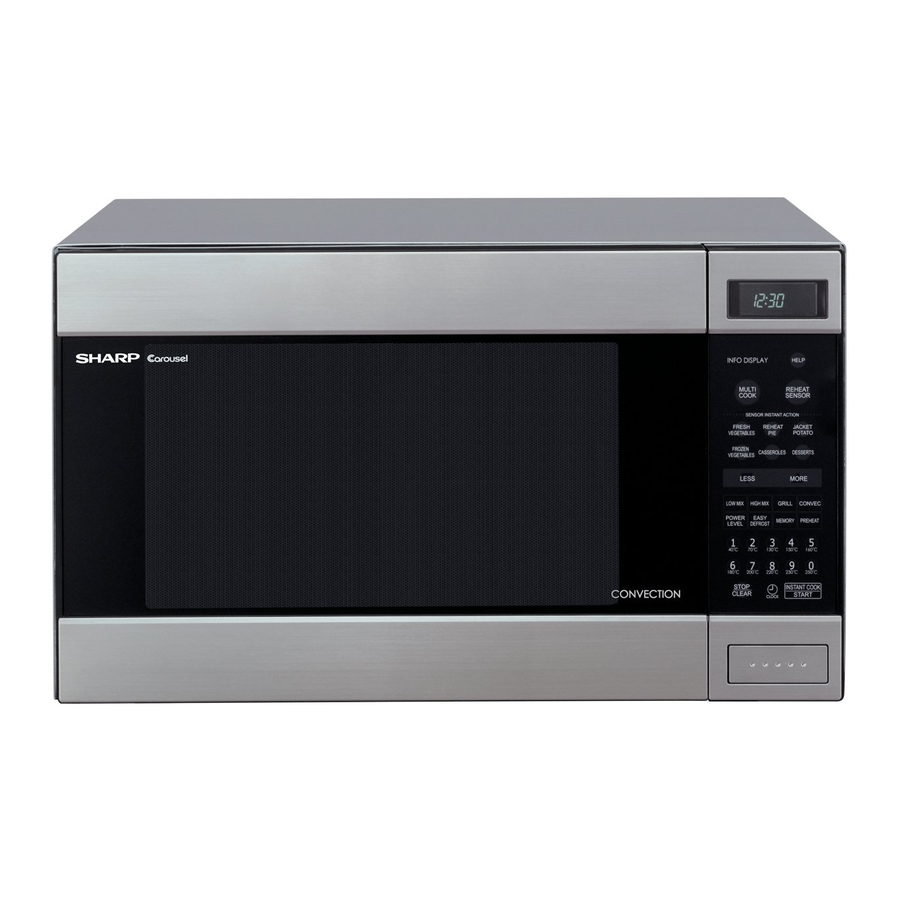
Sharp Carousel R-990KS Посібник з експлуатації - Сторінка 27
Переглянути онлайн або завантажити pdf Посібник з експлуатації для Мікрохвильова піч Sharp Carousel R-990KS. Sharp Carousel R-990KS 48 сторінок. Convection microwave oven
Також для Sharp Carousel R-990KS: Посібник з експлуатації (41 сторінок)

[3] POWER TRANSFORMER REMOVAL
1. REMOVAL
1. CARRY OUT 3D CHECKS.
2. Disconnect the wire leads from power transformer.
3. Disconnect the filament leads of the power transformer from the
magnetron and high voltage capacitor.
4. Disconnect the high voltage fuse from the transformer.
5. Remove the two (2) screws and one (1) washer holding the trans-
former to the base cabinet.
6. Remove the transformer.
2. RE-INSTALL
1. Rest the transformer on the base cabinet with its primary terminals
toward rear cabinet.
[4] MAGNETRON REMOVAL
1. CARRY OUT 3D CHECKS.
2. Disconnect filament lead of transformer and high voltage wire lead
from magnetron.
3. Take off three (3) screws secured the chassis support to oven cav-
ity and waveguide.
4. Remove the cooling fan assembly refer to "Cooling Fan Removal".
5. Carefully remove four (4) mounting screws holding the magnetron
and magnetron air guide to waveguide.
[5] HIGH VOLTAGE RECTIFIER ASSEMBLY REMOVAL
1. CARRY OUT 3D CHECKS.
2. Remove one (1) screw holding the high voltage rectifier terminal to
the capacitor holder.
3. Disconnect the high voltage rectifier assembly from the capacitor.
[6] HIGH VOLTAGE CAPACITOR REMOVAL
1. CARRY OUT 3D CHECKS.
2. Disconnect the high voltage fuse and rectifier assembly from the
high voltage capacitor.
3. Disconnect filament lead of transformer from high voltage capaci-
tor.
[7] OVEN LAMP SOCKET REMOVAL
1. CARRY OUT 3D CHECKS.
2. Pull the wire leads from the oven lamp socket by pushing the termi-
nal hole of the oven lamp socket with the flat type small screw
driver.
3. Lift up the tab of oven lamp mounting plate holding the oven lamp
socket.
4. Slide the oven lamp socket left-ward.
5. Now, the oven lamp socket is free.
[8] HEATER UNIT ASSEMBLY REMOVAL (HEATING ELEMENT/THERMISTOR)
1. HEATER UNIT
1. CARRY OUT 3D CHECKS.
2. Disconnect wire leads from oven thermal cut-out, convection motor,
thermistor and heater element. Remove convection motor assem-
bly refer to "Convection Motor Removal No.3 to No.5".
2. Insert the two edges of the transformer into two metal tabs of the
base cabinet.
3. Make sure the transformer is mounted correctly to the corners
underneath those tabs.
4. After re-installing the transformer, secure the transformer with two
screws to the base cabinet, one is with outertooth washer and the
other is without outer-tooth washer.
5. Re-connect the wire leads (primary) and high voltage fuse to the
transformer and filament leads of transformer to the magnetron and
capacitor, referring to the "Pictorial Diagram".
6. Re-install the outer case and check that the oven is operating prop-
erly.
NOTE: LIVE (ORANGE) WIRE MUST BE CONNECTED TO THE
CABINET-SIDE OF THE POWER TRANSFORMER.
When removing the screws hold the magnetron and magnetron air
guide to prevent it from falling.
6. Remove the magnetron from the waveguide with care so the mag-
netron antenna should not hit by any metal object around the
antenna.
CAUTION: WHEN REPLACING THE MAGNETRON, BE SURE THE
R.F. GASKET IS IN PLACE ANDTHE MAGNETRON
MOUNTING SCREWS ARE TIGHTENED SECURELY.
CAUTION: WHEN
REPLACING
ASSEMBLY, ENSURE THAT THE EARTHING SIDE TER-
MINAL MUST BE SECURED FIRMLY WITH AN EARTH-
ING SCREW.
4. Remove one (1) screw holding the high voltage rectifier from the
capacitor holder.
5. Remove one (1) screw holding capacitor holder to rear cabinet.
6. Remove the high voltage capacitor from the holder.
T erminal
Wire lead
3. Remove eleven (11) screws holding heater duct to the oven cavity.
4. Release two (2) snap bands holding wire harness to the thermal
protection plate (left).
5. The heater unit is now free.
10 – 2
HIGH
VOLTAGE
Oven lamp
s ocket
T erminal hole
F lat type s mall
s crew driver
R990K(W)
RECTIFIER
