Crestron DigitalMedia DM-TX-300N Посібник із швидкого старту - Сторінка 2
Переглянути онлайн або завантажити pdf Посібник із швидкого старту для Передавач Crestron DigitalMedia DM-TX-300N. Crestron DigitalMedia DM-TX-300N 2 сторінки. Digitalmedia transmitters
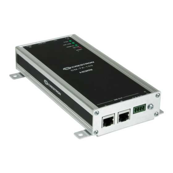
DM-TX-Series
3
Connecting to DigitalMedia Room Controller or DigitalMedia Switcher
Using a DigitalMedia
cable (DM-CBL-P or DM-CBL-NP), connect the
™
transmitter(s) directly to a DigitalMedia Room Controller (if required, first connect
to a DigitalMedia Repeater and then connect the output of the repeater to a room
controller), or connect the transmitter(s) to a DigitalMedia Switcher (via a
DMC-CAT/DMC-F interface card).
NOTE: DigitalMedia cable should have a minimum length of 15 feet (4.6 meters).
1. Configurations with a transmitter connected to a room controller require a
power supply, PW-2407RU, connected either to the transmitter or to the room
controller. For configurations using DM CAT cables, the power supply must be
purchased; for configurations using fiber cable, the power supply is provided.
2. Configurations with a DigitalMedia Switcher may not require an additional
power supply; the switcher typically supplies power for the transmitter. Use the
Crestron Power Calculator to verify that there is enough DMNet power on the
switcher.
3. For detailed instructions on the DigitalMedia Room Controller (DM-RMC-100
and DM-RMC-100-F) or the DigitalMedia Switcher, refer to the latest version
of their respective guides (Doc. 6743, 6744, and 6755) which can be obtained
from the Crestron website (www.crestron.com/manuals).
4
Connecting AV Sources, Outputs, and Verifying Signals
Check that the DM input of the room controller or DigitalMedia Switcher are
connected to the transmitters, and connect/turn on power. Check the transmitter
LEDs, the output display, and verify the signal settings.
•
Check the room controller PWR LED ( on/green).
•
Check the DM LINK LED ( on/green).
•
Check that the VIDEO LED is on/green when a video signal is detected.
The DM-TX-100/100-F does not have video switching because there is only one
AV input.
The DM-TX-200 has auto routing functionality by default:
•
If no signal is present on HDMI IN, RGB IN and AUDIO IN will be
routed.
•
If a signal is present on HDMI IN and no audio is embedded in the
video, (i.e., a DVI signal) HDMI IN video and AUDIO IN audio will be
routed.
•
If a signal is present on HDMI IN with audio embedded in the signal,
HDMI IN audio and video will be routed.
The 300N/300N-F have front panel controls for making selections.
2
For details, refer to the latest revision of the DM-TX-100, DM-TX-200,
and/or DM-TX-300N series DigitalMedia
6741, or 6907, respectively.
QUICKSTART DOC. 6804C (2024043)
DigitalMedia
Transmitters
™
Connection to Room Controller (Fiber)
Power
Supply
(Supplied)
5
Transmitter Guides, Doc. 6810,
™
www.crestron.com
©2010 Specifications subject to
change without notice.
01.10
Connection to Room Controller (DM CAT)
Power Supply
PW-2407RU
(Not Supplied)
OR
24 A B G
Red
Black
Orange
Gnd
Connect the cable from the
Gray
PW-2407 power supply to
either end of the DigitalMedia
"DMNet" Cable, as shown in
From
"DMNet"
PW-2407RU
the diagram to the right.
Control & Power
Fiber Cable
- F
0 0
C - 1
- R M
D M
Setting Up Ethernet
Setup of the IP address for the DigitalMedia transmitters depends on
the way the transmitters are configured within the DigitalMedia system.
1. Transmitters connected to a room controller use their own configu-
ration settings. The units ship in DHCP mode, but the following
static addresses can be set on the units by holding the SETUP
button depressed while the unit boots up:
•
The DM-TX-100, 200, and 300 series units default to
192.168.1.231/232/233.
•
The DM-RMC-100/100-F defaults to 192.168.1.241/242.
NOTE: This process overwrites any current settings. Also, for the
DM-TX-100/100-F, the USB console is enabled and HID functionality
is blocked until reboot.
888.273.7876
201.767.3400
All brand names, product names, and trademarks
are the property of their respective owners.
Connection to DigitalMedia Switcher
0 0
C - 1
D i g
- R M
i t a
D M
S w
l M
e d
i t c
i a
h e
r
CTR
ELE
Power
Supply
(Supplied)
G
UP
LAN
SET
M
CO
HID
IR
USB
S
G
OU
T
B
G
DM
24
A
M
D
I IN
HDM
Power supply
MP
EO
IN
/CO
VID
Y
Pr/C
Pb/
Y
IN
IO
R
(supplied) required
AUD
L
IF
SPD
IO
IN
AUD
R
+ -
for fiber configurations.
+ -
L
G
USA
DVI
-I IN
47
Fiber configurations
NJ
076
T
EIG
H,
I OU
., RO
CKL
HDM
INC
ON
ICS
CTR
ELE
require local power
supplies (supplied).
2. Transmitters connected to a DigitalMedia Switcher are
configured automatically by the switcher.
3. With a PC connected as shown in the diagram below,
use Crestron Toolbox
to set the IP addresses of the
™
transmitter and room controller or DigitalMedia Switcher.
DigitalMedia
Transmitter
PC/Laptop
Cable
OR
Room Controller or
DigitalMedia Switcher
RIC
SHOCK
OUVR
IR
OF
ELECT
NOT
OPEN
E NE
PAS
G
RISK
DO
ELEC
TRIQU
E DE
CHOC
V~7
.0A
RISQU
-250
100
0 Hz
AVIS:
50/6
Fiber
OR
DigitalMedia
2)
(SL
OT
Cable
TPU
TS
OU
DM
US
A
47
, NJ
076
GH
CK
LEI
INC
, RO
ICS
ON
G
UP
LAN
SET
M
CO
HID
IR
USB
G
S
OU
T
B
G
DM
24
A
M
D
I IN
HDM
IN
MP
EO
Pr/C
/CO
VID
Y
Pb/
Y
IN
R
AUD
IO
L
IF
SPD
IO
IN
R
AUD
+ -
+ -
L
G
USA
DVI
-I IN
47
NJ
076
I OU
T
EIG
H,
HDM
., RO
CKL
INC
ON
ICS
CTR
ELE
USB
USB
Cable