Siemens 3AF 01 Інструкція з експлуатації Посібник з експлуатації - Сторінка 7
Переглянути онлайн або завантажити pdf Інструкція з експлуатації Посібник з експлуатації для Промислове обладнання Siemens 3AF 01. Siemens 3AF 01 24 сторінки. Outdoor vacuum switchgear

3
Description
The 36kV 3AF01 vacuum circuit-breakers are designed to
handle all the switching duties that occur in primary
distribution systems. The breakers are extremely reliable
in service, require minimum maintenance and have a
long life expectancy. Moreover, their optimum size and
weight, their quiet and low-vibration operation and the
fact that they are not affected by temperature nor
present a fire risk make the breakers suitable for outdoor
locations.
3.1
Construction (Figs.: 7, 10 & 11)
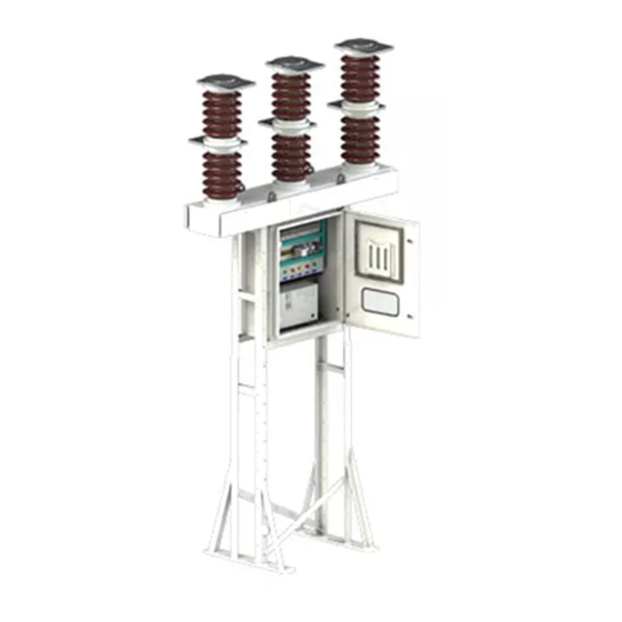
Pole assembly: (Fig. 7)
The vacuum interrupter is mounted in a porcelain
insulator to form an interrupter assembly (P-1, Fig. 7). An
interrupter assembly & a support insulator assembly form
a sealed pole assembly.
Three such assemblies are mounted on a base frame
(P-2, Fig. 7) which has a common operating shaft. This
assembly is mounted on an operating mechanism
housing (P-3, Fig. 7). This is in turn is assembled on steel
structure so as to locate the line terminals at a safe
distance above the ground. The energy storing
mechanism and all the control and actuating devices are
installed in operating mechanism housing. The breaker
can be electrically operated from control room or by
hand locally.
Operating mechanism: (Fig. 11)
The locations of mechanical ON-OFF indicator (P-9,
Fig. 11), the spring charged indicator (P-8, Fig. 11) and
operation counter are shown. Also shown are the 'ON'
push button (P-3, Fig. 11) and 'OFF' push button (P-6,
Fig. 11). This figure also shows the opening to insert the
crank handle (P-15, Fig. 11) which can be used to charge
the spring during maintenance or in case of control
supply failure.
Control panel: (Fig. 10)
On the control panel (P-1, Fig. 10) to the right of the
mechanism is mounted when necessary, the Local/
Remote switch (P-2, Fig. 10) and the breaker ON/OFF
switch (P-3, Fig. 10). Control and signalling cables are
connected to terminal blocks (P-4, Fig. 10) on the panel.
As per wiring diagram, external connections shall be
made on the terminal blocks.
3.2
Vacuum Interrupter (Fig. 9)
The basic construction of the interrupter can be seen in
Fig. 9. The moving contact (P-1) moves in guide
(P-2). The bellows (P-3) follows the travel of contact
(P-1) and seals the interrupter against the surrounding
atmosphere.
The vacuum interrupters fitted in the 3AF 01 vacuum
circuit-breakers are type-approved in accordance with the
X-ray regulations of the Federal Republic of Germany.
They conform to the requirements of the X-ray
regulations of January 8, 1987 (Federal Law Gazette
Page 144) § 8 and Annex III Section 5 up to respective
rated short-time AC voltage stipulated in accordance with
VDE/IEC (rated power frequency withstand voltage).
3.3
The Arc quenching Principle
When the contacts separate, the current to be
interrupted initiates a metal vapour arc discharge and
flows through this plasma until the next current zero. The
arc is then extinguished and the conductive metal vapour
condenses on the metal surfaces within a matter of
microseconds. As a result, the dielectric strength in the
break builds up very rapidly.
The contacts are designed so that the self generated field
causes the arc to travel. This prevents their local
overheating when interrupting large current.
The metal vapour arc discharge can only be maintained if
a certain minimum current flows. A current that does not
attain this level is chopped prior to current zero. The
chopping current must be kept to a minimum in order to
prevent unduly high over voltages building up when
inductive circuits are switched. The use of a special
contact material ensures that current chopping is limited
to 4-5 A.
The rapid build-up of the dielectric strength in the break
enables the arc to be safely extinguished even
if contact separation occurs immediately prior to current
zero.
The arc drawn in the vacuum interrupter is not cooled.
The metal vapour plasma is highly conductive and the
resulting arc voltage only attains value between 20 and
200 V. For this reason and because of the short arcing
time, the arc energy developed in the break is very small.
This also accounts for the long electrical life expectancy
of the vacuum interrupter.
3.4
Switching Operation
When a closing command is initiated, the closing spring
(P-12, Fig. 11) which was previously charged (by hand or
by the motor), actuates the moving contact through the
drive shaft (P-20, Fig. 7), pull rod (P-4, Fig. 7), switching
shaft (P-5, Fig. 7) and switching rod (P-6, Fig. 7).
During closing, the tripping spring (P-13, Fig. 11) and the
contact pressure springs (P-19, Fig. 7) are charged. The
closing spring of motor operated breaker is recharged
(within 15 seconds) after CB is closed.
In the closed state, the necessary contact pressure is
maintained by the contact pressure springs and the
atmospheric pressure. The contact pressure spring
automatically compensates for contact erosion, which is
very small.
When a tripping command is given, the energy stored in
the tripping and contact pressure springs is released. If
the breaker is to be tripped locally, the tripping spring is
released by pressing the OFF button (P-6, Fig. 11). In the
case of an electrical command being given, the tripping
solenoid Y1 (P-5, Fig. 11) unlatches the tripping spring.
The opening sequence is similar to the closing sequence.
The residual force of the tripping spring arrests the
moving contact in the open position.
In the event of the control supply failing, the breaker can
be operated by hand.
The anti-pumping device in the form of an auxiliary
contactor in the operating mechanism for the breaker
ensures that it is not repeatedly opened and closed in the
event of simultaneous ON and OFF commands.
5
