Siemens 3VT Series Інструкція з експлуатації Посібник з експлуатації - Сторінка 3
Переглянути онлайн або завантажити pdf Інструкція з експлуатації Посібник з експлуатації для Промислове обладнання Siemens 3VT Series. Siemens 3VT Series 15 сторінок. 3vt switch disconnector
Також для Siemens 3VT Series: Інструкція з експлуатації Посібник з експлуатації (6 сторінок), Інструкція з експлуатації (4 сторінок), Інструкція з експлуатації Посібник з експлуатації (10 сторінок), Інструкція з експлуатації Посібник з експлуатації (8 сторінок)

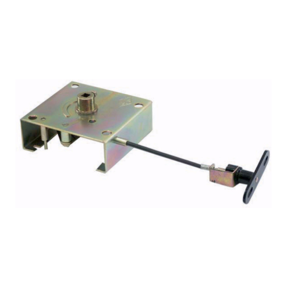
Accessory for 3VT circuit-breakers — Interlock between rotary mechanism and compartment door
Safety Instructions
Read and understand these instructions before installing,
operating, or maintaining the equipment.
DANGER
!
Hazardous voltage.
Will cause death or serious injury.
Disconnect power before working on equipment.
CAUTION
Reliable functioning of the equipment is only ensured with
certified components.
The status indications ("ON", "TRIPPED", "OFF") of the circuit-
breaker and the "RESET" position are indicated on both the
operating panel as well as on the rotary handle.
All rotary operating mechanisms can be locked in the OFF posi-
tion with the help of suitable padlocks. All 3VT circuit-breakers
equipped with rotary operating mechanisms may be used as
main devices. Rotary operating mechanisms can be interlocked
with the switchgear cabinet door to avoid opening the door when
the circuit-breaker is closed.
Installation of the interlock between the rotary mechanism and
the compartment door for the VT250
(1) Step 1: Remove the label from the accessory cover.
(2) Step 2: Remove the screws under the label of the front
cover.
(3) Step 3: Remove the screws under the front cover.
(4) Step 4: Screw the rotary operating mechanism onto the cir-
cuit-breaker.
(5) Step 5: Attach the operating shaft.
(6) Step 6: Attach the rotary handle.
(7) When the circuit-breaker is in the ON position, the key
tongue will lock the compartment door.
(8) The rotary handle is in the ON position.
(9) Key tongue.
(10) When the circuit-breaker is in the OFF position, the key
tongue will allow the compartment door to be opened.
(11) The rotary handle is in the OFF position.
(12) Key tongue.
Installation of the interlock between the rotary mechanism and
the compartment door for the VT400
(13) Step 1: Remove the label from the accessory cover.
(14) Step 2: Remove the screws under the label of the front
cover.
(15) Step 3: Remove the screws under the front cover.
(16) Step 4: Screw the rotary operating mechanism onto the cir-
cuit-breaker.
(17) Step 5: Attach the operating shaft.
(18) Step 6: Attach the rotary handle.
(19) When the circuit-breaker is in the ON position, the key
tongue will lock the compartment door.
(20) The rotary handle is in the OFF position.
(21) Key tongue.
(22) When the circuit-breaker is in the OFF position, the key
tongue will allow the compartment door to be opened.
A5E00817832-01
(23) The rotary handle is in the OFF position.
(24) Key
tongue.
Installation of the interlock between the rotary mechanism and
the compartment door for the VT630
(25) Step 1: Remove the label from the accessory cover.
(26) Step 2: Remove the screws under the label of the front
cover.
(27) Step 3: Remove the screws under the front cover.
(28) Step 4: Screw the rotary operating mechanism onto the cir-
cuit-breaker.
(29) Step 5: Attach the operating shaft.
(30) Step 6: Attach the rotary handle. When the circuit-breaker is
in the ON position, the key tongue will lock the compartment
door. When the circuit-breaker is in the OFF position, the
key tongue will allow the compartment door to be opened.
(31) The rotary handle is in the OFF position.
(32) Key tongue.
Dimension drawings
(33) Dimension drawing of the interlock between the rotary
mechanism and the compartment door for the VT250 and
the VT400.
(34) Dimension drawing of the interlock between the rotary
mechanism and the compartment door for the VT630.
English
3
