Siemens SIMATIC ET 200S Посібник користувача - Сторінка 22

Переглянути онлайн або завантажити pdf Посібник користувача для Промислове обладнання Siemens SIMATIC ET 200S. Siemens SIMATIC ET 200S 26 сторінок. Distributed i/o digital electronic module 4do dc24v/2a hf
Також для Siemens SIMATIC ET 200S: Посібник оператора (18 сторінок), Посібник (16 сторінок), Посібник користувача (16 сторінок), Посібник (37 сторінок), Посібник (24 сторінок), Посібник з експлуатації (40 сторінок), Інструкція з експлуатації (4 сторінок), Оригінальна інструкція з експлуатації (19 сторінок), Оригінальна інструкція з експлуатації (20 сторінок), Посібник (34 сторінок), Посібник (14 сторінок), Посібник (24 сторінок), Оригінальна інструкція з експлуатації (17 сторінок), Оригінальна інструкція з експлуатації (19 сторінок), Посібник (16 сторінок), Посібник (28 сторінок), Посібник (12 сторінок), Посібник (32 сторінок), Посібник (18 сторінок), Посібник (12 сторінок), Посібник (28 сторінок), Посібник (22 сторінок), Посібник (22 сторінок), Посібник (36 сторінок), Посібник (16 сторінок)
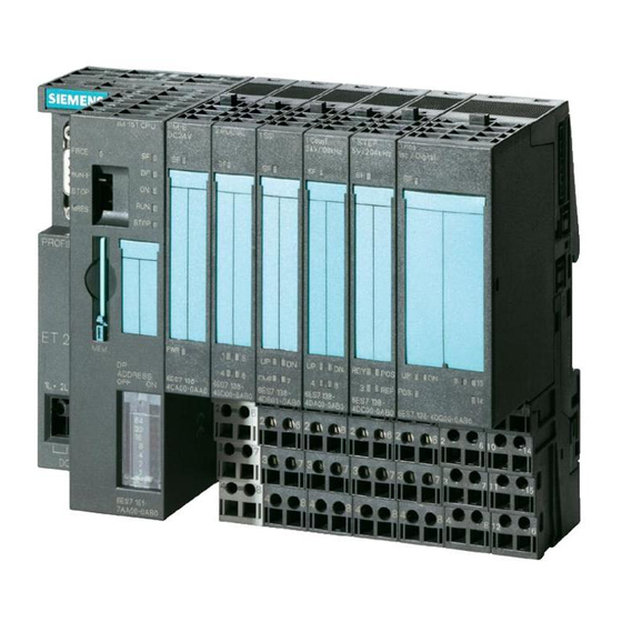
Siemens SIMATIC ET 200S Посібник користувача
Connecting
5.1 Connecting measuring sensors
Abbreviations used
The meanings of the abbreviations in the figures below are as follows:
M+:
M-
M
ANA
M
L+
U
CM
U
ISO
Isolated measuring encoders
The isolated measuring encoders are not connected to the local ground potential. These can
be potential-free. Depending on local conditions or interference, potential differences U
(static or dynamic) can occur between the measuring lines M- of the input channels and the
reference point of the measuring circuit M
The permitted value for U
interference.
The following schematic representation illustrates the connection of isolated measuring
encoders to the optically isolated analog input modules.
5
22
Measuring line (positive)
Measuring line (negative)
Reference potential of the analog measuring circuit
Ground connection
Rated load voltage 24 V DC
Potential difference between inputs and reference potential of the measuring
circuit M
ANA
Potential difference between M
must not be exceeded, even in environments with strong EMC
CM
4
Logic
Backplane bus
Ground bus
Central grounding point
Isolated measuring encoders
and central grounding point
ANA
.
ANA
1
3
2AI U HF analog electronic module (6ES7134-4LB02-0AB0)
2
Manual, 04/2007, A5E01076007-01
CM