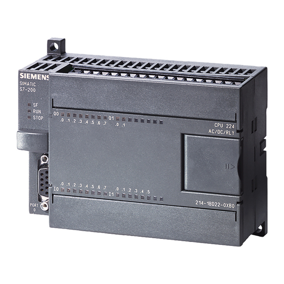
Siemens SIMATIC S7-200 Посібник - Сторінка 12
Переглянути онлайн або завантажити pdf Посібник для Промислове обладнання Siemens SIMATIC S7-200. Siemens SIMATIC S7-200 30 сторінок. Ethernet gateway for simatic mpi/ profibus driver
Також для Siemens SIMATIC S7-200: Посібник (35 сторінок), Посібник водія (28 сторінок), Посібник (49 сторінок), Посібник (18 сторінок), Посібник користувача системи (20 сторінок)

Program conversion process
2.4 Compare the symbols/tags in the original program and the converted program
Local symbols
● STEP 7-Micro/Win local symbols are defined in the Local variable tables of the main
● The converted STEP 7 Basic local symbols are defined in the Block interface table of the
Table 2- 3
Symbol conversion rules
STEP 7-Micro/WIN program
symbolic reference
I, Q, or M memory symbol
AIW and AQW (Analog I/O symbols)
HC symbol name
(High-speed counter)
SM and S memory symbols
V memory symbol
T (timer memory) and
C (counter memory
L memory symbol
(Local variable table)
Note
STEP 7-Micro/WIN wizard and library symbols
The symbols used in subroutines, interrupt routines, and V memory data groups (data block
tabs) created by STEP 7-Micro/WIN wizards or library usage are not converted. Also,
symbols used in user-protected POUs or V memory tabs are not converted.
Unconverted code blocks and data block tabs (data groups) can create undefined symbols in
POU blocks that were successfully converted. You must define these symbols to use
symbolic addressing in substitute program logic.
12
routine, subroutines, and interrupt routines.
corresponding OBs (Organizational blocks) and FCs (Functions).
Converts to this STEP 7 Basic PLC tag
PLC Tag table I, Q, and M memory tags
PLC Tag table I and Q memory tags
PLC Tag table I memory tag
Undefined program parameter
The S7-1200 does not have SM or S
memory. Define the parameter name in
substitute program logic.
In the program editor, a red squiggle
underline indicates an undefined
parameter name.
The V memory symbol name becomes
a DB1 data block element name, or the
S7-200 V memory symbol is discarded
because it overlapped the address of
another V memory symbol.
Timer and counter symbol names
become the DB names of the data
blocks associated with the converted
timer and counter instructions.
L memory symbol
(Block interface table)
STEP 7 Basic programming issues
The I/O base addresses can be modified
by PLC Device configuration and can
make the converted S7-200 address
incorrect.
Make a Tag table entry (I, Q, M, or
•
constant):
In the program editor, right-click on
the parameter name and select
"Define tag".
Make a data block reference:
•
Change the undefined symbol name
to a data block address.
Ex. DB1.SymV0_1
A discarded S7-200 V memory symbol
creates an undefined parameter in
converted program logic. You must
assign a new symbol name and DB1
address.
In S7-1200 LAD programs, The Q
•
output of counter and timer boxes
replaces the function of the S7-200
counter and timer bit addresses.
Timer and counter bits/current values
•
can also be accessed as data
elements within the associated DB.
SIMATIC S7-200 to SIMATIC S7-1200 software conversion tool
Manual, 1/2010
