Siemens Simatic S7-300 Початок роботи - Сторінка 13

Переглянути онлайн або завантажити pdf Початок роботи для Промислове обладнання Siemens Simatic S7-300. Siemens Simatic S7-300 16 сторінок. Automation systems, controlling a physical axis
Також для Siemens Simatic S7-300: Посібник користувача (34 сторінок), Посібник (21 сторінок), Інструкція з експлуатації (4 сторінок), Інструкція з експлуатації (5 сторінок), Посібник (35 сторінок), Початок роботи (8 сторінок), Опис програми (24 сторінок), Посібник (18 сторінок), Посібник (32 сторінок), Посібник з встановлення та обладнання (20 сторінок), Початок роботи (32 сторінок)
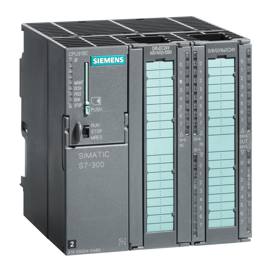
Siemens Simatic S7-300 Початок роботи
3.3

3. Step: Setting parameters

Procedure
1. Start the parameter assignment interface with SIMATIC/STEP7/PID Control Parameter
2. In PID control, open your project with "File > Open". Select instance DB 101 for SFB 41.
3. Close the parameter assignment screen form with "File > Close".
4. In SIMATIC Manager, select "SIMATIC 300 Station > CPU 3xx > S7 Program > Blocks".
5. Download all of the S7 blocks it contains to your CPU via "PLC > Download" (CPU in
3.4

4. Step: Trial run

Procedure
1. In the "Blocks" directory, double-click on the variable table "VAT1" in your project.
2. Go online with "PLC > Connect to > Configured CPU".
3. Activate monitoring with "Variable > Monitor".
4. Switch the CPU to RUN.
5. Modify the setpoint "SP_INT".
6. Call the STEP 7 tool PID Control (see step 3). Select instance DB 101 and click "Online"
Getting Started - Commissioning a CPU 31xC: Closed-loop control
Getting Started, 08/2011, A5E00105534-03
Assignment.
The input dialog "PID Control" is displayed.
Acknowledge the dialog with "OK".
You are returned to the parameter assignment screen form. The configured parameters
are displayed. Changes to this sample program are not required.
The parameter assignment screen form is closed.
All blocks of the S7 program are displayed.
STOP mode).
The program and configuration are downloaded from the PG to the CPU.
The variable table for monitoring and modifying is displayed.
At the bottom right, you will see that the CPU is set to "STOP" mode.
The current values of the addresses are displayed in the "Status Value" column.
At the bottom right, you will see that the CPU is set to "RUN" mode. The controller is
started.
You can monitor the output value "OUTV" that is proportional to the setpoint "SP_INT".
mode. In the "Test" menu, select and start the "Curve plotter" function.
You can view the graphic profile of some of the control variables (actual value, setpoint,
control offset, etc.).
Learning units
3.3 3. Step: Setting parameters
13