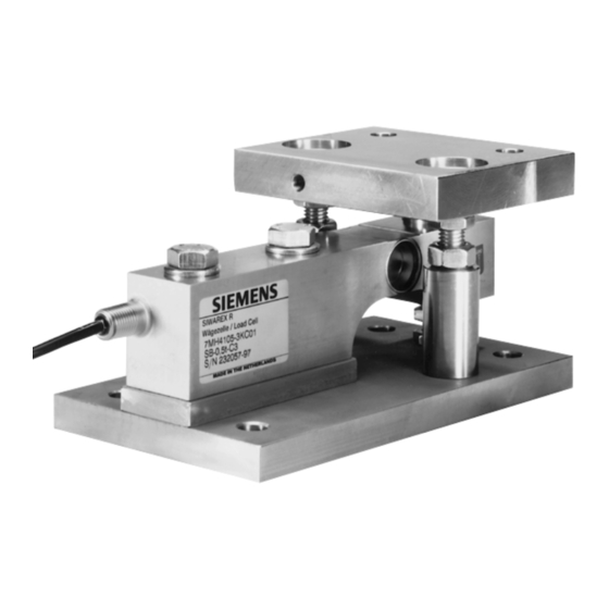
Siemens SIWAREX R Інструкція з експлуатації Посібник з експлуатації - Сторінка 24
Переглянути онлайн або завантажити pdf Інструкція з експлуатації Посібник з експлуатації для Промислове обладнання Siemens SIWAREX R. Siemens SIWAREX R 38 сторінок. Mounting units for sb series
Також для Siemens SIWAREX R: Інструкція з експлуатації Посібник з експлуатації (34 сторінок)

Revision 09/04
Assembly procedure: (numbering see Fig. 3-2)
1.
Load cell preparation:
•
A data sheet is supplied with every load cell with the calibration values for that
load cell. This is found in a supply pocket which is stuck on the packaging. Take
the data sheet and store it in a safe place.
•
Unpack the load cell.
2.
Combination Mounting Unit preparation:
NOTE
The lifting path of the top plate (18) must be set from approximately 3 mm with
the counter-sunk bolts (9), see dimension X in Fig. 3-4 Setting this lifting path is
easier if performed before installing the load cell. The combination mounting unit
must be disassembled in order to install the load cell.
The combination mounting units are pre-assembled before delivery. Adjust the
top plate (18) using the two countersunk bolts (9) and the two nuts (7) to the
following mounting height:
Rated load
functional installation height
+ lifting distance
= installation height
These preparations and following the handling procedures as described in the
following prevent any extra work in adjusting later.
When using the combination mounting units as dummies, this 3 mm of extra
height is to be taken into account or it can be adjusted later.
•
Unpack the combination mounting unit.
Scope of delivery:
•
Set the lifting distance of the top plate (18) as described above.
•
Install the top nuts (7) onto the lower nuts (6) and tighten.
•
Loosen the lower nuts (6) and unscrew the countersunk bolts (9) from the base
plate (1). Leave the countersunk bolts (9) in the top plate (18), do not loosen the
nuts (6) and (7) put the top plate (18) to the side.
•
Check the flat seal (15) for proper seating.
•
Smear the ball surface of the pendulum bolt (16) with bearing grease.
3.
Assemble the Combination Mounting Unit:
NOTE
Please follow the guidelines from chapter 1.5 Load Cell Handling when working
with load cells.
CAUTION
An incorrect or incomplete assembly can result in damaging load cells, mounting
components and the loading platform.
Document No.: A5E00353789B
- combination mounting unit, assembled
- Pendulum bolt (16)
- Oscillation housing (12) with flat seal (15) and retaining ring (12)
Comb. Mounting Units
0.5 t, 1 t, 2 t
5 t
105 mm
140 mm
3 mm
3 mm
108 mm
143 mm
Page 24
