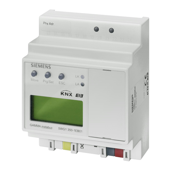
Siemens 5WG1 350-1E 801 Технічна інформація про продукт - Сторінка 3
Переглянути онлайн або завантажити pdf Технічна інформація про продукт для Контролер Siemens 5WG1 350-1E 801. Siemens 5WG1 350-1E 801 4 сторінки. Gamma instabus

IP Controller N350E
Location and Function of the Display and
Operator Elements
Figure 1: Location of the display and operator elements
A1 AC/DC 24 V bus connector terminal (yellow-white)
A2 KNX bus connector terminal (black-red)
A3 Ethernet RJ45 socket
A4 KNX programming LED
A5 KNX learning button
A6 Display 2x12 characters
A7 MOVE push button
A8 Set/Prg push button
A9 ESC push button
A10 Ethernet Link LED
A11 Ethernet Activity LED
A12 Battery case
Setting time and date
In the display mode the LC-display shows time, day of
week, and date. Switch to the setup mode by depressing
the Set/Prg-push button (A8). Hour – Minute – Day –
Month – Year can be set in this order. Move from one to
the next with the Set/Prg-push button (A8). The selected
time/date value can be set by depressing the Move push
button (A7). Scroll through until the correct value is
displayed and then press the Set/Prg-push button (A8) to
move to the next time/date value.
After you entered the value for the year press the
Set/Prg-push button (A8). The device automatically
leaves the setup mode after approximately five seconds.
The setup mode can be left by pressing the ESC push
button (A9).
Siemens AG
Infrastructure & Cities Sector, Building Technologies
Control Products and Systems
P.O. Box 10 09 53, D-93009 Regensburg
Mounting and Wiring
General description
The N-system DIN-rail device can be installed in distribu-
tion boards, surface or flush mounted, or on any DIN rail
complying with EN 60715-TH35-7,5.
The connection to the bus line is established via the bus
connector terminal (red-black) on the top side.
The RJ45 socket on the device front side provides the
connection to the Ethernet-IP data network.
Mounting DIN-rail devices (Figure 2)
Slide the device (Figure 2, B1) onto the DIN-rail (Figure
-
2, B2) and
swivel back the device until the slide clicks into place
-
audibly.
Connect the auxiliary power AC/DC 24V with the yel-
-
low-white bus connector terminal (A1).
Connect the bus line with the black-red bus connector
-
terminal (A2).
Plug an Ethernet patch cable with an RJ45 plug into
-
the RJ45 socket (A3) to connect the device with the
LAN / Intranet.
A connection is established to the network when the
yellow LED marked LK (A10) is continuously lit. When
the LED LA (A11) flashes data is sent to or from the de-
vice.
Dismounting DIN-rail devices
Unplug the Ethernet patch cable from the RJ45 socket
-
(Figure 1, A3).
Remove the yellow-white bus connector terminal (Fig-
-
ure 1, A1) from its socket.
Remove the black-red bus connector terminal (Fig-
-
ure 1, A2) from its socket.
press down the slide (Figure 2, C3) with a screw-driver
-
and
swivel the device (Figure 2, C1) from the DIN-rail (Fig-
-
ure 2, C2).
B2
B1
Figure 2: Mounting and dismounting a DIN-rail device
N350E, 4 Seiten
© Siemens AG 2013
Subject to change without further notice
GAMMA instabus
Technical Product Information
February 2013
5WG1 350-1EB01
C2
C1
C3
Technical manual
Update: http://www.siemens.com/gamma
2.12.1.12/3
