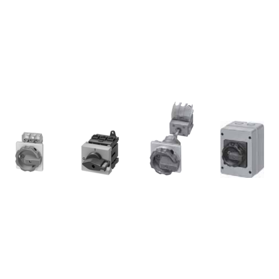
Siemens 3KA58 Брошура - Сторінка 18
Переглянути онлайн або завантажити pdf Брошура для Перемикач Siemens 3KA58. Siemens 3KA58 50 сторінок. Switch disconnectors and fuses

SENTRIC NP Fuse Switch Disconnectors
General data
■
Technical specifications
Standards
Type
Rated uninterrupted current I
For fuse links acc. to DIN 43620
Continuous thermal current I
Rated operating voltage U
AC 50 Hz/60 Hz
DC
Rated insulation voltage U
Rated impulse withstand voltage U
Rated conditional short-circuit current with fuses
(on rapid closing)
With fuse links
Rated current
at AC 400 V (690 V)
Maximum permissible let-through I
Permissible let-through current of the fuse
Short-circuit strength with fuses
(with closed disconnector)
7
With fuse links
Rated current
at 690 V
Permissible let-through current of the fuse
Rated making and breaking capacity
(Feed-in from top or bottom)
At AC 400 V, with fuse links
or isolating links
Rated breaking current I
Rated operating current I
AC-21B, AC-22B
AC-23B
At AC 500 V, with fuse links
or isolating links
Rated breaking current I
Rated operating current I
AC-21 B
AC-22B
AC-23B
At AC 690 V, with fuse links
or isolating links
Rated breaking current I
Rated operating current I
AC-21 B
AC-22B
AC-23B
At DC 220 V/240 V, with fuse links
or isolating links
Rated operating current I
220 V DC-23B/DC-21B
440 V DC-21B
1) 125/160 A only with 3NY1 236 supply terminals and with 21 mm wide fuse
links 3NY1 822 (125 A) and 3NY1 824 (160 A); see Accessories.
2) Only for isolating links; otherwise note instructions of the fuse manufac-
turer.
3) For no-load switching (AC-20 B, DC-20 B), DC voltages up to DC 690 V
can be applied.
4) For safety monitoring max. 690 V.
5) For pollution severity 2, the switch disconnectors can be used up to 1000 V
AC-20 B, DC-20 B (no-load switching).
6) Conducting paths in series: 3 at 3NP40; 2 at 3NP42, 3NP43 and 3NP44.
7/18
Siemens LV 10 · 2004
A
u
Size
A
th
e
V
V
V
i
kV
imp
Size/A
kA (rms value)
2
2
t value
kA
s
kA (peak value)
Size/A
kA (rms value)
kA (peak value)
Size
(p.f. = 0.35)
A (rms value)
c
at
e
A
A
Size
(p.f. = 0.35)
A (rms value)
c
at
e
A
A
A
Size
(p.f. = 0.35)
A (rms value)
c
at
e
A
A
A
3)5)6)
Size
at
e
A
A
IEC 60947-1, IEC 60947-3, VDE 0660 Part 107
3NP40 1
3NP40 7
1)
160
160
00C/000
00
1)
160
160
690
220
(3 conducting paths in series)
690
690
6
6
000/100 (35)
00/160
50 (50)
50
56 (7.8)
158
11 (5)
15
000/100
00/160
100
50
15
15
000
00
800 (p.f. = 0.45)
800
160
160
100
100
000
00
320 (p.f. = 0.45)
320
160
160
100
100
40
40
000
00
200/240
200/240
(p.f. = 0.45/0.95)
(p.f. = 0.45/0.95)
160
160
50
50
25
25
000
00
80/160
80/160
–
–
3NP42 7
3NP43 7
3NP44 7
250
400
630
1 and 0
2 and 1
3 and 2
250
400
630
690
440
(2 conducting paths in series)
4)
4)
800
800
800
6
6
6
1/250
2/400
3/630
50
50
50
551
1515
4340
25
35
55
1/250
2/400
3/630
50
50
50
25
35
55
1
2
3
2000
3200
5040
250
400
630
250
400
630
1
2
3
750
1200
1890
250
400
630
250
400
630
–
–
–
1
2
3
375
600
945
250
400
630
–
–
–
–
–
–
1
2
3
–
–
–
250
400
630
4)
