Siemens SIMATIC S7-1200 Інструкція з експлуатації Посібник з експлуатації - Сторінка 14

Переглянути онлайн або завантажити pdf Інструкція з експлуатації Посібник з експлуатації для Перемикач Siemens SIMATIC S7-1200. Siemens SIMATIC S7-1200 36 сторінок. Controlling several fans (ebm-papst) via modbus rtu
Також для Siemens SIMATIC S7-1200: Посібник (30 сторінок), Інструкція з програмування безпеки (48 сторінок), Посібник (40 сторінок), Посібник (17 сторінок), Посібник (31 сторінок), Посібник (49 сторінок), Посібник (20 сторінок)
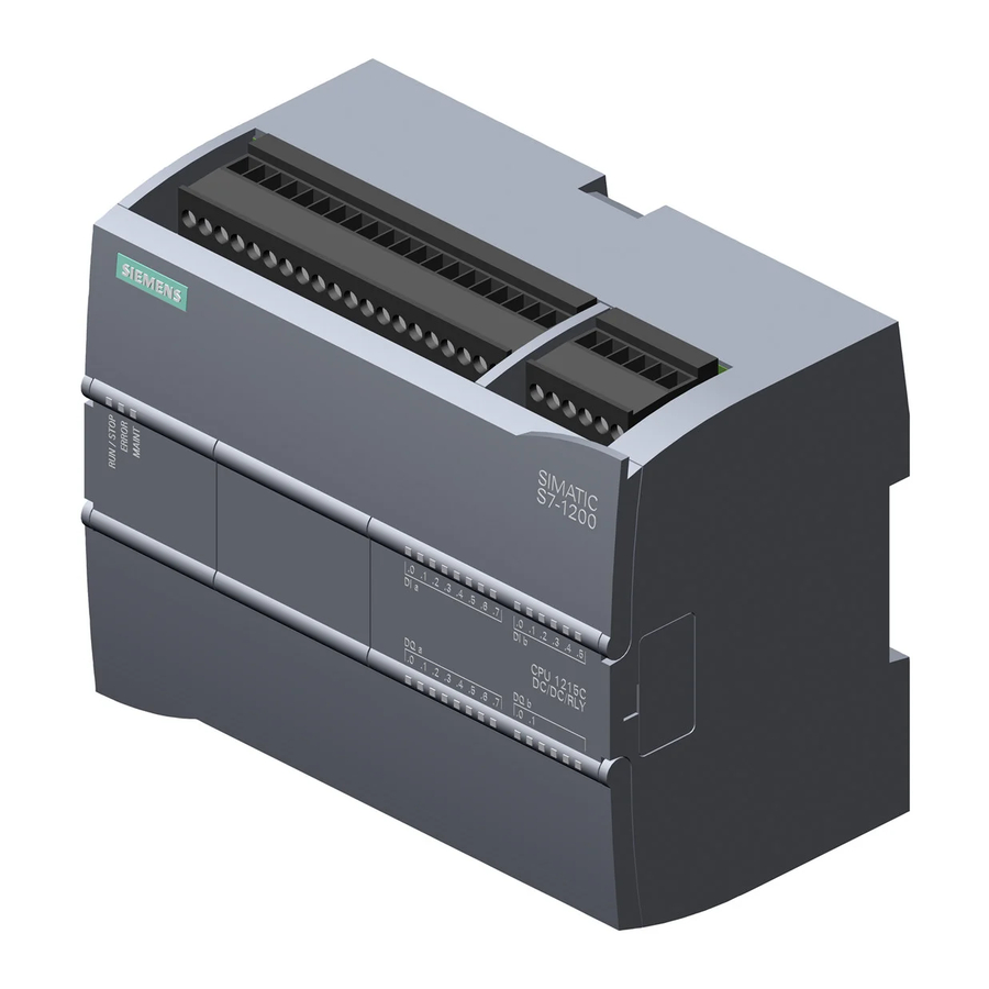
Siemens SIMATIC S7-1200 Інструкція з експлуатації Посібник з експлуатації
Product characteristics
3.4 TP ports
NOTICE
TP cords or TP-XP cords with a maximum length of 10 m can be connected to the RJ-45
TP port.
With the IE FC cables and IE FC RJ-45 plug 180, an overall cable length of up to 100 m is
permitted between two devices depending on the cable type.
Autonegotiation
Autonegotiation means the automatic detection of the functionality of the port at the opposite
end. Using autonegotiation, network components or end devices can detect the functionality
available at the port of a partner device allowing automatic configuration of different types of
device. With autonegotiation, two components connected to an Ethernet segment can
exchange parameters and set themselves to match the supported communication
functionality.
Note
Devices not supporting autonegotiation must be set to 100 Mbps/ half duplex or 10 Mbps half
duplex.
Note
The CSM 1277 is a plug-and-play device that does not require settings to be made for
commissioning.
Auto polarity exchange
If the pair of receiving cables are incorrectly connected (RD+ and RD- swapped over), the
polarity is adapted automatically.
MDI /MDIX autocrossover function
The advantage of the MDI /MDIX autocrossover function is that straight-through cables can
be used throughout and crossover Ethernet cables are unnecessary. This prevents
malfunctions resulting from mismatching send and receive wires. This makes installation
much easier for the user.
Insulation between the ports
There are two port groups:
Group1: P1 and P2
Group2: P3 and P4
Between ports of different port groups, an insulation voltage of 1.5 kV is adhered to
(corresponds to IEEE802.3 Section 33.4.1.1, Environment B). For example between P1 and
P4.
14
Compact Switch Module CSM 1277
Operating Instructions, V. 1.20, A2B00079397B