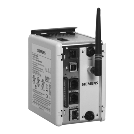
SITRANS RD500 - 8 CHANNEL 0(4)-20 mA INPUT MODULE
GENERAL DESCRIPTION
The 16-bit analog input module is designed for use with the SITRANS RD500.
The module provides a means of high-density signal measurement for data-
acquisition applications. The module accepts 0/4-20 process signals.
The module connects and communicates via a backplane connection to the
SITRANS RD500. The RD500 supports any combination of up to 16 modules, allowing
a total of 128 signals to be monitored via a single RD500.
Internal power management circuits allow the modules in non-hazardous
locations to be replaced while power is applied, which reduces downtime. All
configuration information is stored locally within the module, as well as in the
RD500, so replacement modules do not need to be configured.
The SITRANS RD500 high density packaging and DIN rail mounting saves time
and panel space. The backplane connection provides power and communication
to the module and snaps easily onto standard top hat (T) profile DIN rail.
DIMENSIONS In inches (mm)
1.24
(31.5)
4.98
(126.5)
13
7
1
Internet Explorer is a registered trademark of the Microsoft Corporation in the
United States and/or other countries.
Firefox is a registered trademark of Mozilla Foundation.
7ML19985MB01
DEDICATED HIGH DENSITY INPUT MODULE FOR THE
MODEL ACCEPTS 0/4-20 mA
FULLY SCALABLE
UNUSED INPUTS CAN BE DISABLED TO INCREASE
MODULE AUTO DETECTABLE BY SITRANS RD500
AUTO ADDRESSING MINIMIZES CONFIGURATION TIME
CAN BE USED IN CONJUNCTION WITH ANY SITRANS
CONFIGURATION
Explorer
RD500's IO, log data to the supported compact flash card, monitor connected
instruments for alarm conditions and send scheduled reports and data via FTP
sync or email.
SAFETY SUMMARY
manual or on equipment must be observed to ensure personal safety and to
prevent damage to either the instrument or equipment connected to it. If
equipment is used in a manner not specified by the manufacturer, the protection
provided by the equipment may be impaired.
not equipped with safeguards. To do so can be potentially harmful to persons or
equipment in the event of a fault to the module. An independent and redundant
temperature limit indicator with alarm outputs is strongly recommended.
4.17 (105.9)
GENERAL SPECIFICATIONS
1. POWER: Derived from system backplane. (75 mA load on power input of RD500).
2. LEDs:
SITRANS RD500
SITRANS RD500
OVERALL READING RATE
RD500 MODULES
Sitrans RD500 is configured using standard browser software such as Internet
®
®
and Firefox
.
Through the onboard web server users are able to remotely configure the
Please see RD500 application manual for further details.
All safety related regulations, local codes and instructions that appear in the
Do not use the module to directly command motors, valves, or other actuators
CAUTION: Risk of Danger.
Read complete instructions prior to
installation and operation of the unit.
WARNING - EXPLOSION HAZARD - SUBSTITUTION OF
COMPONENTS MAY IMPAIR SUITABILITY FOR CLASS I, DIVISION 2
THIS EQUIPMENT IS ONLY SUITABLE FOR USE IN NON-HAZARDOUS
OR CLASS I, DIVISION 2, GROUPS A, B, C, D, LOCATIONS
Module may be hot-swapped (replaced while powered up in non-hazardous
locations).
STS - Status LED shows module condition.
ALM - Alarm LED is lit during any internal alarm condition.
CAUTION: Risk of electric shock.
Page 1

