Siemens TSM-1X Інструкція з монтажу
Переглянути онлайн або завантажити pdf Інструкція з монтажу для Перемикач Siemens TSM-1X. Siemens TSM-1X 4 сторінки. Intelligent test switch module with dual isolators
Installation Instructions
Models TSM-1X
Intelligent Test Switch Module with Dual Isolators
INTRODUCTION
The Model TSM-1X Intelligent Test Switch Module, P/N
S54370-B7-A1, from Siemens Industry, Inc. is an
addressable, key-activated momentary switch (T-45)
with a tri-color LED indicator for use with intelligent
duct detectors or other compatible intelligent devices on
the Device Loop Circuit of Desigo
FC2025/FC2050/FV2025/FV2050 and Cerberus PRO
FC922/FC924/FV922/FV924 Fire Alarm Systems
(refer to Figure 1). The key activation will cause its
associated intelligent duct detectors or other smoke
detectors and compatible devices to go into alarm.
This alarm condition will cause all logic associated
with the duct detector to activate. The 3-color LED of
the module will show the status of its associated
intelligent duct detector. The TSM-1X is mounted on a
switch plate and can be installed in a 3½ inch deep
single gang box.
The TSM-1X module supports two operation modes:
polarity insensitive mode and isolator mode. The
module can be wired for either mode (refer to Figures
3 to 4). During the isolator mode, the built-in dual
isolators will work at both sides of the module to
isolate the line short in front or behind the module.
Observe precautions for handling
Electrostatic Sensitive Devices.
PROGRAMMING
1. Refer to Figure 2 to locate the programming
holes on back of the TSM-1X.
2. To connect the TSM-1X to the DPU
Programmer/Tester, insert the plug from the DPU
cable provided with the Programmer/ Tester into
the programming holes.
3. To prevent potential damage to the DPU, DO
NOT connect a TSM-1X to the DPU until all
conductors of the same polarity are removed from
the device line of the TSM-1X.
4. Follow the steps in the DPU Manual, P/N 315-
033260, to program the TSM-1X to the desired
address. Record the device address on the label
located on the side of the TSM-1X module.
5.
Add a logic function in the system configuration
tool, Document ID A6V10315023, with the
intelligent duct detector or other compatible
intelligent devices that will be tested. The TSM-1X
can now be installed and wired to the system.
A6V101055486_en--_a
firealarmresources.com
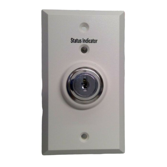
Figure 1
TSM-1X Intelligent Test Switch Module
Figure 2
Connecting to the DPU Plug
Siemens Industry, Inc.
Building Technologies Division
Florham Park, New Jersey
Programming holes
are polarity insensitive -
Plug can be inserted
in any direction.