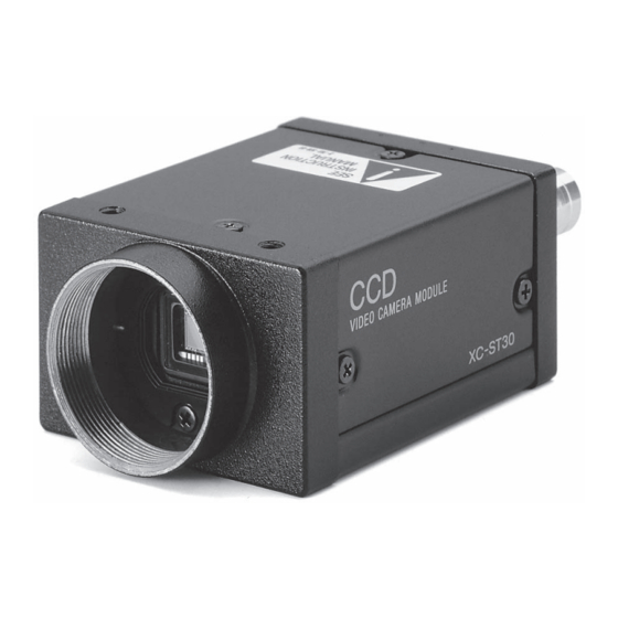
Sony XC-ST51 Посібник - Сторінка 3
Переглянути онлайн або завантажити pdf Посібник для Цифрова камера Sony XC-ST51. Sony XC-ST51 4 сторінки. Black-and-white video camera module
Також для Sony XC-ST51: Технічний посібник (30 сторінок)

Rear Panel
1
2
3
4
5
1 HD/VD signal input/output switch
Set the switch to INT to output HD/VD signals from the camera
module. Set the switch to EXT to input HD/VD signals from an
external unit. (Factory setting: EXT)
2 VIDEO OUT (Video signal output) connector (BNC)
You can use this connector for video signal output from the
camera module.
3 γ compensation ON/OFF switch
Turn on this switch for g compensation. (Factory setting: OFF)
4 GAIN switch
This switch selects AGC (A), fi xed gain (F), or manual gain control
(M). (Factory setting: F)
5 Manual gain control
Adjust the gain using this control. GAIN switch 4 must have been
set to M (Manual).
6 Shutter speed/Mode setting DIP switch
1 Shutter speed (bits 1 to 4)
Set an appropriate shutter speed. (Factory setting: Shutter off)
2 High-rate scan mode switch (bit 5)
Factory setting: FRAME
3 Restart reset/External trigger shutter mode switch (bits 6 to 8)
Factory setting: Normal
Note
•
Do not use any other settings for Restart reset/External trigger
shutter mode except those shown on the next page. Using other
settings may cause the camera to malfunction.
•
If you set the External trigger shutter mode, set 0 in bits 1 to 4.
7 75 Ω termination switch
Turn off if you do not terminate. (Factory setting: ON)
8 TRIG polarity switch
Select + or – according to the trigger pulse input from an external
unit. (Factory setting: +)
9 DC IN/SYNC (DC power input/sync signal I/O) connector
(12-pin)
Connect a CCXC-12P05N camera cable to this connector the
+12 V DC power supply and the video signal output from the
camera module. When a sync signal generator is connected to this
connector, the camera module is synchronized with the external
sync signals.
Factory Mode Settings of Rear Panel
No. Switch
1 HD/VD signal input/output switch
3 γ compensation ON/OFF switch
4 GAIN switch
5 Manual gain control
Shutter speed (bits 1 – 4)
Shutter speed/Mode
Potential accumulation mode (bit 5)
6
setting DIP switches
Restart reset/External trigger shutter
mode switch (bits 6 – 8)
7 75 Ω termination switch
8 TRIG polarity switch
1) This unit is shipped from the factory with the GAIN switch being set to F (fi x), so the Manual
gain control knob is not operative unless the switch setting is changed. When the GAIN switch
is set to M (manual), you can rotate this knob to adjust gain over the range 0 to 18 dB.
72
XC-ST70/ST70CE/ST50/ST50CE/ST51/ST51CE/ST30/ST30CE
9
8
7
6
Factory setting mode
EXT
OFF
F
1)
–
OFF
(All S/W are left
side)
ON
+
Connector Pin Assignments
Rear panel
Pin
Camera sync
External mode
External mode
No.
output
(VS)
Ground
Ground
Ground
1
2
+12 V DC
+12 V DC
+12 V DC
3
Video output (Ground) Video output (Ground) Video output (Ground) Video output (Ground) Video output (Ground)
4
Video output (Signal) Video output (Signal) Video output (Signal) Video output (Signal) Video output (Signal)
5
HD output (Ground) HD input (Ground)
6
HD output (Signal) HD input (Signal)
7
VD output (Signal) VD input (Signal) VS input (Signal) Reset (Signal)
8
—
—
9
—
—
10
—
—
11
—
—
VD output (Ground) VD input (Ground) VS input (Ground) Reset (Ground) Reset (Ground)*
12
* Common ground for pins 7, 10, and 11
About the Electronic Shutter
There are two shutter types: normal shutter and external trigger
shutter. Select them with the DIP switches on the rear panel.
DIP Switches on the Rear Panel
Rear panel
Switches 1 to 4: Shutter speed
Switch 5:
Potential accumulation mode
Switches 6 to 8: Restart reset/External trigger shutter mode switch
Normal Shutter
This mode provides continuous video output with the electronic
shutter selected by switches to capture a high-speed moving
object clearly.
Normal shutter speed settings
Shutter
1/125
1/250
OFF
1/2000
1/4000
1/10000
* If you set the mode to fl ickerless, the positions of DIP switches 1 to 3 are optional.
Note
The DIP switch 5 position is optional. (The fi eld setting is
recommended.) The fi eld setting can obtain a sensitivity that is
twice that of the frame setting.
External
Restart/Reset
(VS)
trigger shutter
Ground
Ground
+12 V DC
+12 V DC
—
HD input (Ground) HD input (Ground)
—
HD input (Signal)
HD input (Signal)
VD input (Signal)
—
—
—
—
—
—
WEN output (Signal)
—
—
Trigger pulse input (Signal)
—
—
DIP switches
1/500
1/1000
Flickerless*
1/100 (EIA)
1/120 (CCIR)
(Unit: second)
