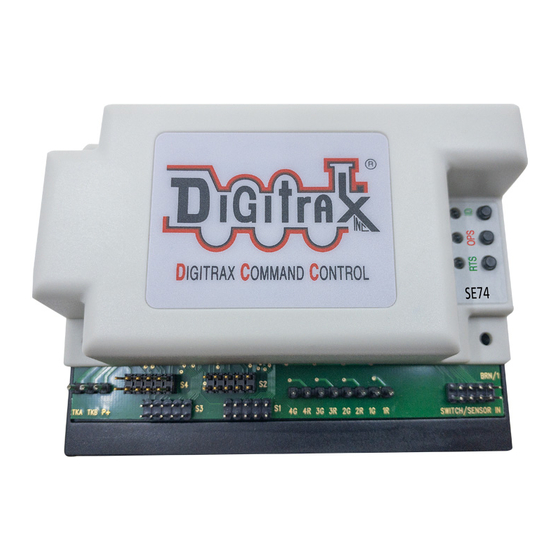
Digitrax SE74 Посібник - Сторінка 10
Переглянути онлайн або завантажити pdf Посібник для Конвертер мультимедіа Digitrax SE74. Digitrax SE74 12 сторінок.

2.
These six wiring diagrams show how to connect the signal LED leads you
have into a SE1 cable to display LED aspects. SE74 defaults support the
provided Digitrax test mast with no OPSW changes needed.
3.
Figure 4 shows a PCB test mast with; two 3-color G type heads, 100 ohm
current-setting resistors and 10-pin plug. This mast is used for test and
debugging the operation of SE74 A1/A2 (Dwarf) heads. Rotated 180 degrees
on the cable this test mast acts like Figure 5; as B/C signal heads on any
SE1 cable. The test mast is wired for common anode operation as shown in
Figure 4. The lunar LEDS are shown for wiring detail, and are not installed
on the PCB test mast.
Mast Base PCB
FIGURE 4: Test Mast Dual 3 color heads with lunars
4.
The 3-wire Searchlights of Figures 6 and 7 are common cathode version and
allow Lunar lamps to be connected for all 4 heads on an SE1 cable.
FIGURE 6: A/D direction Dual 3-wire searchlight heads with lunars
5.
The 2-wire searchlight examples in Figures 8 and 9 need OPSW33 =C and do
© 2022 Digitrax, Inc.
A1 Mainline
Common Anode
D/ A2: Diverging
Dwarf
D Lunar
A1 Lunar
common anode/OPSW35 =T
A1 Mainline
D/ A2: Diverging
Dwarf
D Lunar
A1 Lunar
common cathode/OPSW35 = C
Mast Base PCB
FIGURE 5: B/C direction Dual 3 color heads with lunars
FIGURE 7: B/C direction Dual 3-wire searchlight heads with lunars
— 10 —
C Siding
Common Anode
B Mainline
B Lunar
C Lunar
common anode/OPSW35 =T
C Siding
B mainline
B Lunar
C Lunar
common cathode/OPSW35 = C
www.digitrax.com
